The Latest Versions of IEC 60601-2-25:2011 and -2-27:2011: Big Changes to the Defibrillation Protection Test
In 2011, the latest versions of IEC 60601-2-25 ed. 2.0, Electrocardiographs; and IEC 60601-2-27 ed. 3.0, Electrocardiographic Monitoring Equipment, were released. Both standards have the identical test for Defibrillation Protection, and they have been significantly revised from their previous versions for this test. A new switch, named S3 in the standard has been added, a resistor value has been changed from 470k to 390k, and the circuit topology has been changed, for the common mode test.
February 28, 2012
In 2011, the latest versions of IEC 60601-2-25 ed. 2.0, Electrocardiographs; and IEC 60601-2-27 ed. 3.0, Electrocardiographic Monitoring Equipment, were released. Both standards have the identical test for defibrillation protection, and they have been significantly revised from their previous versions for this test. A new switch, named S3 in the standard has been added, a resistor value has been changed from 470k to 390k, and the circuit topology has been changed, for the common mode test. For both common and differential mode tests, the test requires that the test pulses be delivered in a proscribed time period of 20 seconds between pulses. For the common mode test, five pulses of each polarity are delivered with 20 seconds between pulses. For the differential mode test, the test is repeated for each lead wire in turn, until all lead wires are tested.
|
Jeff Lind |
It also appears that the tolerance of the test components has been increased to ±1% for this test, see Para. 201.5.4. In the previous edition, we assumed a tolerance of ±5% was required by these components by reference to a similar Figure in IEC 60601-1 (see IEC 60601-1:2005 Fig. 9). This reference was necessary because it appeared to us that no tolerances were assigned to the load-carrying components making up the circuit (see IEC 60601-2-27:2005, Para 17h.101.3 and Fig. 108).
The new test package for -2-25:2011 and -2-27:2011 is quite a bit more stringent than the old test. Regulatory engineers will have to ensure that the resistor circuit value of 470kΩ is changed to the new value of 390kΩ. Since the topology of the common mode test has changed, regulatory engineers will also have to modify their defibrillation protection testers to add in S3 and lift the connection between the bottom node of the 100Ω resistor and ground while the common mode is connected, and replace the connection for the differential mode. Please note also that S3 is a in a high voltage, high current portion of the circuit and should be suitably sized.
Of greater concern is the new repetition rate of 20 seconds between tests. We have checked and we do not believe any cycle times have been assigned to this test in past versions of this standard, or other standards in the IEC 60601-x universe. If the test is conducted at this repetition rate using a tester not rated for this duty cycle, the resistors will heat and fall out of tolerance, making test results inconclusive.
Further, the accuracy of the resistors have gone from an assumed tolerance of ±5% to a required tolerance of ±1%. This is a big improvement for defibrillation protection testers because it is a brand new tolerance, much more stringent than the tolerance of similar circuits in tests described in the overall Standard IEC 60601-1.
|
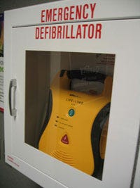
Emergency defibrillator image from Olaf on Flickr. |
Existing defibrillation protection testers will need to be updated to meet this new requirement.
A note on resistor tolerance: While it appears that the resistor tolerance noted in the new IEC 60601-2-25:2011 of ±1% is for the resistors at rest (cold, before testing), another important tolerance is the drift experienced by the resistor bank while it heats, during the test; which is not addressed in the IEC Standards. It’s important to keep the drift within a reasonable amount during the test sequence. (We have assumed that the drift of the resistor bank should stay within the specification noted in IEC 60601 during the pulsing cycle in the past, so we have assumed a 5% drift as being the requirement in our equipment.) Since the new 20 second duty cycle is faster than anticipated by defibrillation protection Testers currently on the market, regulatory engineers should test their defibrillation protection testers to see if the resistor bank will stay within comfortable tolerance. This test can be done by pulsing the defibrillation protection Tester every 20 seconds with nothing connected to the output, so the whole pulse appears across the 100Ω resistor. Repeat this test ten times to simulate the new common mode test. If a resistance measurement of the 100 ohm resistor is taken just before the next pulse is delivered, the engineer can see what tolerance can be held by the tester, and make a determination of acceptability.
As a final note, we are designing our defibrillation protection tester to meet the new requirements, and are assigning a resting tolerance to the 100Ω resistor of 1%, and a working tolerance of 5% over a duty cycle of 20 seconds continuous. We believe this is a valid interpretation of IEC 60601-2-25 and -27. Should discussion ensue we are most interested.
—Jeff Lind
Jeff is the president of Compliance West USA (San Diego, CA)
You May Also Like


.png?width=300&auto=webp&quality=80&disable=upscale)
