Leakage-Current Testing for Patient-Monitoring Devices
For developers of patient-monitoring equipment, including external defibrillators, it is critical to understand the complex tests required under IEC 60601-2-49.
June 1, 2007
ELECTRONICS
Some of the most challenging leakage-current-testing requirements are those for patient-monitoring devices—both invasive and noninvasive. Such testing can be time-consuming and expensive, so it is essential to understand the rationale and requirements of these tests and how to apply them appropriately. It is important for manufacturers to understand the application of leakage-current testing required for compliance with IEC 60601-2-49.
IEC 60601-2-49, “Particular Requirements for the Safety of Multifunction Patient Monitoring Equipment,” amends and supplements the general IEC 60601-1 standard, “Medical Electrical Equipment, Part 1: General Requirements for Safety.” IEC 60601-2-49 introduces new terms, such as part leakage current and single function, that are not discussed in the general IEC 60601-1 standard. The new terms are used because applied parts are viewed in terms of function and type, and isolation between functions and types.
Unlike IEC 60601-1, for which certification agencies have national deviations that amend or override the IEC version, there is no deviation to this standard. By default, all agencies use IEC 60601-2-49 to determine compliance for devices such as patient monitors and external defibrillators.
Scope
IEC 60601-1 contains the basic requirements for medical device safety. However, some devices have additional requirements that extend beyond the general 60601-1 standard. For these devices, detailed standards, called particular standards, identify requirements that amend or override the requirements of the general standard. If no requirements are specifically stated in the particular standard, then the default requirements for a device come from the general standard.
Subclause 2.2.101 of IEC 60601-2-49 defines multifunction patient monitoring equipment as a
Modular or preconfigured device including more than one physiological monitoring unit designed to collect information from a single PATIENT and process it for monitoring purposes and to generate ALARMS.
The standard applies to equipment having either more than one applied part or more than one single function. Such equipment is intended for connection to a single patient for the purpose of monitoring physiological functions. Also, medical devices in compliance with this standard must have only Type BF (bodily floating) and Type CF (cardiac floating) applied parts. These are considered F-Type, or floating, applied parts. BF applied parts are minimally invasive and are not intended for direct cardiac application. By contrast, CF applied parts, which are considered highly invasive, are parts intended for direct cardiac application.
Understanding the relationship between an applied part, a single function, and a patient connection is perhaps the single most important aspect of intuitively understanding the reasoning and rationale behind determining which leakage current tests are applicable for a particular device design.
An applied part is a part of the equipment that in normal use contains one or more of the following characteristics:
Necessarily comes into physical contact with the patient for the equipment to perform its function.
Can be brought into contact with the patient.
Needs to be touched by the patient.
Other important terms include single function and patient connection. Single function is the measurement of one physiological parameter. Patient connection is defined as “every individual part of the applied part through which current can flow between the patient and the equipment in normal condition or in single-fault condition.”
An applied part may have a single function, and the single function can have multiple patient connections. For example, a five-lead electrocardiograph (ECG) is a single-function device with five patient connections.
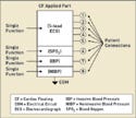
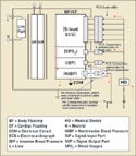
However, an applied part can also have more than one single function, and each single function can have multiple patient connections. For example, a patient monitor might have an ECG function as well as functions for measuring blood oxygen (SPO2), invasive blood pressure (IBP), and noninvasive blood pressure (NIBP). These are all separate single functions, but they could be part of the same applied part circuit with the same electrical circuit reference, commonly referred to as COM.
|
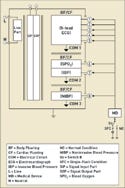
Figure 1. (click to enlarge) An applied part with multiple single functions. |
In Figure 1, one CF applied part has multiple single functions all tied to the same common reference point. The ECG, SPO2, IBP, and NIBP circuits are all designed as part of the same circuit. In this case, there are potential leakage-current paths between the single functions. These paths must be tested as required in subclauses 19.3 dd and 19.3 ee.
Common single functions in the same applied part introduce the issue of part leakage current. This type of current is defined as “the current flowing from a single function through the patient to the remaining single functions of the same applied part under normal condition.” The single functions may not be part of the same applied part.
|
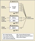
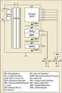
Figure 2. (click to enlarge) Multiple applied parts. |
By contrast, there may be multiple applied parts on the medical device, as illustrated in Figure 2. In this figure, the patient monitor has separate applied-part circuits. The ECG single function now becomes its own CF applied part with five patient connections. The SPO2 and IBP circuits have been designed into a separately isolated applied part with two single functions having one patient connection for each single function.
The Tests
For IEC 60601-2-49, applied parts are viewed in terms of function and type, and isolation between functions and types. To verify proper isolation and separation of functions and applied part types, the standard uses specialized leakage-current testing configurations. These configurations verify isolation of single functions, applied parts, and applied part types.
Leakage currents are measured flowing into and out of the patient connections. To obtain these measurements, the patient connections are grouped according to applied part, applied part type, or single functions in several configurations.
The leakage current is measured in normal condition, flowing out of the patient connections to ground (source leakage). This measurement is done to verify that excessive leakage is not induced from one or more single functions or applied parts into another single function. It also verifies that the leakage is not induced from the applied part as a result of the patient being in a normal-condition grounded state.
Leakage current is also measured in a single-fault condition in which the current flowing into the patient connection is measured as a result of mains voltage applied to the applied part (sink leakage). This measurement is done to verify that other single functions or applied parts do not cause a conductive path in which excessive leakage current will flow as a result of the patient being in a single-fault condition state where the patient is at mains voltage.
Device manufacturers must understand how these tests are applied. The following sections refer to the subclauses and figures found in IEC 60601-2-49.
Multiple Applied Parts
|
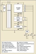
Figure 3. (click to enlarge) BF applied parts tested in all combinations of Sa (open) and Sb (single-fault condition). Redrawn from IEC 60601-2-49, Figure KK.101. |
Type BF Applied Parts. Subclause 19.3 aa and Figure KK.101 address Type BF applied parts (see Figure 3). These parts are tested from and to all patient connections of an applied part connected together.
Medical devices can have multiple applied parts, so multiple isolation barriers must be evaluated. The particular standard specifies how to test devices with multiple applied parts, whereas the general standard does not.
For this test, sink all single functions to ground while measuring all BF applied parts of a single function tied together in normal condition and in a single-fault condition.
IEC 60601-1 does not specify methods for testing devices with multiple functions. Because multiple functions and applied parts may be separated by isolation barriers, new hazards are introduced that need to be addressed. It is critical to verify that leakages from other functions and other applied parts do not collectively cause excessive leakage of another single function or applied part. Because it is considered a normal condition for a patient connection to be grounded, patient leakage current as a result of separate applied parts must be tested in both normal and single-fault conditions.
For BF applied parts, multiple patient connections of the applied part being tested can be connected to the same measurement point at the same time. However, for CF applied parts, each patient connection of an applied part must be measured individually. Because CF applied parts are intended for use in direct cardiac applications, the leakage current limits are reduced, and each lead must be measured separately. Patient leakage current limits for this test shall not exceed those given in Table IV of the IEC 60601-1 general standard. For example, according to the table, BF patient leakage shall not exceed 100 µA ac and 10 µA dc in normal condition. CF patient leakage shall not exceed 10 µA ac or dc in normal condition. The invasiveness of a CF applied part reduces leakage by a factor of 10.
|
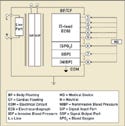
Figure 4. (click to enlarge) CF applied parts tested in all combinations of Sa (open) and Sb (single-fault condition). Redrawn from IEC 60601-2-49, Figure KK.102. |
Type CF Applied Parts. Subclause 19.3 bb and Figure KK.102 of IEC 60601-2-49 focus on Type CF applied parts. These parts must be tested from and to every patient connection of the applied part (see Figure 4).
Like the general IEC 60601-1 standard, the particular standard requires CF applied parts to be evaluated separately. Each lead must be evaluated separately because of the invasiveness of such medical devices. An applied part that will be used in direct cardiac contact must be scrutinized carefully.
For this test, sink all single functions to ground and measure individual CF patient connections of an individual single function in normal condition and in single-fault condition.
IEC 60601-1 does not specify methods for testing devices that have more than one monitoring function. Because multiple functions and applied parts may be separated by isolation barriers, the leakage current flowing through these insulation barriers must be evaluated in both normal and single-fault conditions. It is considered normal condition for a patient connection to be grounded, so the issue of patient leakage current as a result of separate applied parts must be tested in normal condition and in single-fault condition.
For CF applied parts, the patient connections of the applied part must be tested separately. Patient leakage-current limits for this test shall not exceed those given in Table IV of the IEC 60601-1 general standard.
|
Figure 5. (click to enlarge) BF or CF applied parts with Sb in normal and in single-fault condition. Redrawn from IEC 60601-2-49, Figure KK.103. |
Type BF or Type CF Applied Parts. These combinations are addressed in subclause 19.3 cc and in Figure KK.103 of IEC 60601-2-49. In these cases, parts must be tested for all patient connections of only Type BF or of only Type CF applied parts connected together (see Figure 5).
This test is similar to the patient leakage and patient F-type leakage tests required in the general IEC 60601-1 standard. It evaluates the total leakage current and assumes the device has only BF or only CF applied parts. The total leakage current is the vector sum of all of the individual leakage currents tied to all of the applied parts of the same type.
The current being measured is flowing out of all applied parts of the same type in normal condition. It is also the current flowing into all applied parts of the same type in single-fault condition with mains voltage on the applied parts.
For this test, connect all applied parts and patient connections of Type BF and measure in both normal and single-fault conditions. Then, connect all applied parts and all patient connections of Type CF and again measure in both normal condition and single-fault condition.
|
Table I. (click to enlarge) Maximum total patient leakage currents. Data from Table 101 in IEC 60601-2-49. |
It is important to remember that the applied parts in the medical device must be all Type BF or all Type CF for this test to be applicable. Leakage limits are listed in Table I.
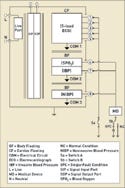
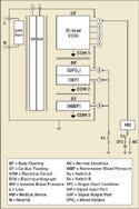
Type BF and CF Applied Parts. Subclause 19.3 cc and Figure KK.104 of IEC 60601-2-49 address measuring leakage current of devices that have both Type BF and CF applied parts. The parts must be tested for all patient connections of the same type connected together (see Figures 6 and 7).
The tests in subclause 19.3 cc and represented in Figure KK.103 of the standard evaluate the total leakage current of a device with only type BF or only type CF applied parts. For Figure KK.104, however, a device may have both BF and CF applied part types. In this case, Type BF and Type CF applied parts are tested by tying together all patient connections of the same applied part type.
|
Figure 6. (click to enlarge) Medical device on highly invasive CF parts tested in all combinations of Sb. Redrawn from IEC 60601-2-49, Figure KK.104. |
These tests are then performed both in normal and in single-fault conditions. BF applied parts are evaluated separately from the CF applied parts. However, in this situation, while the BF applied parts are evaluated in normal and in single-fault condition, the CF applied parts are connected to ground and then to mains voltage. When the CF applied parts are evaluated, the BF applied parts are connected to ground and then to mains voltage.
|
Figure 7. (click to enlarge) Medical device on minimally invasive body floating (BF) parts tested in all combinations of Sb. Redrawn from IEC 60601-2-49, Figure KK.104. |
Connect all applied parts and patient connections of Type BF and sink them to ground. In both normal condition and in single-fault condition, measure all of the applied parts and patient connections of Type CF that are connected together.
Then connect all applied parts and patient connections of Type BF, and apply mains voltage to them. Measure all of the applied parts and patient connections of Type CF connected together both in normal condition and in single-fault condition. Connect all applied parts and patient connections of Type CF and sink them to ground. Then, in normal condition and in single-fault condition, measure all the applied parts and patient connections of Type BF connected together. Connect all applied parts and patient connections of Type CF, and apply mains voltage to them. Then measure all applied parts and patient connections of Type BF connected together in normal condition and in single-fault condition. With multiple applied parts in a medical device, each applied part can contribute to the total leakage current, which is the vector sum of the leakage current from each individual applied part. Leakage current limits are listed in Table I.
Part Leakage Current
Subclauses 19.3 dd and 19.3 ee and Figures KK.105 and KK.106 examine part leakage current. This test may appear to be the same as the patient auxiliary current test in the IEC 60601-1 general standard. However, this test assesses part leakage current as an extraneous leakage current caused by voltage differences between single functions. Type BF applied parts are tested between any patient connection of a single function and the remaining single functions of the same applied part connected together (see Figure 8).
|
Figure 8. (click to enlarge) Part leakage for BF applied part. Redrawn from Figures KK.105 and KK.106. |
For this test, connect any patient connections of Type BF and measure the leakage flowing to all the other patient connections of the same applied part tied together. For BF applied parts, the patient connections are pulled together and included in the measurement of the applied part under test.
Each single function of the same applied part must be evaluated against all other single functions on the same applied part. For example, the ECG function must be evaluated with all other functions connected together. Then, SPO2 must be evaluated with all of the other applied parts connected together. The part leakage current limit for BF applied parts is 0.01 mA dc or 0.1 mA ac.
In contrast to subclause 19.3 dd, this subclause requires that all patient connections of the CF applied part in a single function be evaluated independently while connecting all other functions together.
Type CF applied parts must be tested between any single patient connection of a single function and all other patient connections of the same applied part connected together. Connect any single patient connection on a single function of type CF and measure the leakage flowing to all the other functions tied to the same applied part. The part leakage current limit for CF applied parts is 0.01 mA dc or 0.1 mA ac.
Patient Connectors
|
Figure 9. (click to enlarge) Total patient leakage. Redrawn from Figure KK.107. |
Subclause 19.3 ff and Figure KK.107 of the standard focus on leakage current for patient connectors. This leakage-current test is a unique requirement because it specifically calls for the patient connectors to be tested for patient leakage current (see Figure 9). For this standard, the applied part is not just at the medical device. The leads and connectors must be considered as an extension of the applied part. This makes sense because the leads and connectors also come into direct contact with the patient. A partially or completely unplugged lead could expose the pins inside the connector, making it possible for the patient to come directly into contact with the current.
Any connector in a lead that has a conductive connection to the equipment must be tested if it does not meet the requirement in subclause 56.3 aa. This subclause states that the part must have an air clearance of 0.5 mm from any pin to another pin or to the flat surface of the connector. If the pin is 0.5 mm or greater from the outer flat end of the connector or to any other pin, it is considered unlikely to come into contact with a person or with any other pin and, therefore, it does not have to be evaluated.
|
Table II. (click to enlarge) Maximum total patient leakage current for patient connectors. Data from Table 102 in IEC 60601-2-49. |
In this test, the leakage-current measurement must be taken in single-fault condition between different single functions of the same applied part. Attach the equipment connectors of a single function to ground and then connect all of the remaining patient connections of that same applied part to 110% mains voltage for a single-fault condition. The patient leakage current limit is listed in Table II.
Conclusion
Although this article uses an ECG to illustrate the test configurations, it is important to understand that other types of devices, such as external defibrillators, also fall within the scope of the standard. The standard applies to equipment as defined in subclause 2.2.101.
To know when and how to apply this standard, device manufacturers must clearly understand the definitions and relationships of applied parts, single functions, and patient connections. Understanding the design and location of the isolation barriers between single functions and applied parts is crucial for correctly applying the newly introduced part leakage and total leakage-current testing.
The testing can be time-consuming and repetitive, especially for multiple CF applied parts and functions. Care should be taken to ensure that the connections are made reliably and correctly each time. With a better understanding of the IEC 60601-2-49 standard, manufacturers can more readily determine which tests are appropriate for a given product and how to apply them correctly.
Jeff St. Onge is chief engineer for the medical division at QuadTech Inc. (Maynard, MA).
References
1. UL 60601-1, 2nd ed., “Medical Electrical Equipment—Part 1: General Requirements for Safety” (Northbrook, IL: Underwriters Laboratories, 2003).
2. IEC 60601-2-49, 1st ed., “Particular Requirements for the Safety of Multifunction Patient Monitoring Equipment,” (Geneva: International Electrotechnical Commission, 2001).
Copyright ©2007 Medical Device & Diagnostic Industry
About the Author(s)
You May Also Like



.png?width=300&auto=webp&quality=80&disable=upscale)
