With advances in both computing speed and simulation software capabilities, finite element analysis (FEA) has been increasingly adopted and integrated into the design process of complex medical devices. It has been shown that the proper use of FEA can greatly improve both the speed and the quality of product design as well as reduce the overall cost.
Rubber parts such as silicone diaphragms, septums, seals, valves, tubing, and balloons are critical components in many of today’s medical devices. FEA can be an excellent tool for design engineers to improve the functional performance of these devices.
FEA for rubber products is far more complex than for metal and plastic products. It requires sophisticated nonlinear FEA software as well as a good understanding of the material behavior, material modeling, and testing requirements. The intent of this article is to address some of these special issues and to help medical device engineers to use FEA more effectively as a design tool for rubber products.
Types of Nonlinearities
It is well known that nonlinear FEA is essential for rubber products. Typically, in such an analysis, the following three types of nonlinearities are encountered:
Kinematic nonlinearity.
Material nonlinearity.
Boundary nonlinearity.
|
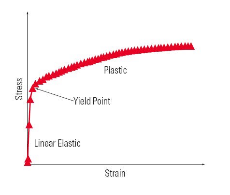
Figure 1. Stress versus strain of metal and plastics. |
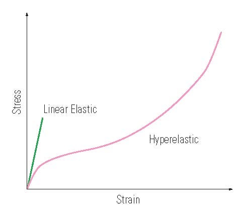
In the vast majority of instances, rubber products are subject to large deformations. Whenever a material experiences large deformations, at least two kinds of nonlinearity—kinematic and material—are involved. When one says that metals or plastics are linear materials, it means that these materials have a linear stress-strain relationship when the strain is very small. The slope of the relationship is represented by Young’s Modulus, E. Beyond this elastic strain range, metals and plastics do show a type of nonlinear behavior referred to as plasticity. However, the nonlinear behavior of rubber is different from metals and plastics, as shown in Figures 1 and 2.
Commonly used nonlinear material models in FEA are, therefore, elastoplastic models for metals and plastics and hyperelastic models for rubber, respectively.
In addition, the boundary nonlinearity is usually associated with large deformations. For example, during installation of an O-ring into tube joint, the O-ring is subjected to large compression and frictional contact with its mating parts, and it will be further deformed by fluid pressure during operation. In these processes, the O-ring keeps changing shape and interacts nonlinearly with the boundary loading from the mating parts or fluid pressure. Even for this seemingly simple problem, FEA is very challenging, especially when there is a relative motion at contact surfaces between the O-ring and the mating parts.
|
Figure 2. Stress versus strain of rubber. |
Dealing with kinematic nonlinearity and modeling various types of material nonlinearities have been basic features of advanced nonlinear FEA software. However, individual software capability of dealing with difficult contact problems does vary. In evaluating and selecting an FEA package for rubber products, it is important to pay particular attention to its contact element capability.
Mechanical Property and ?Modeling of Rubber
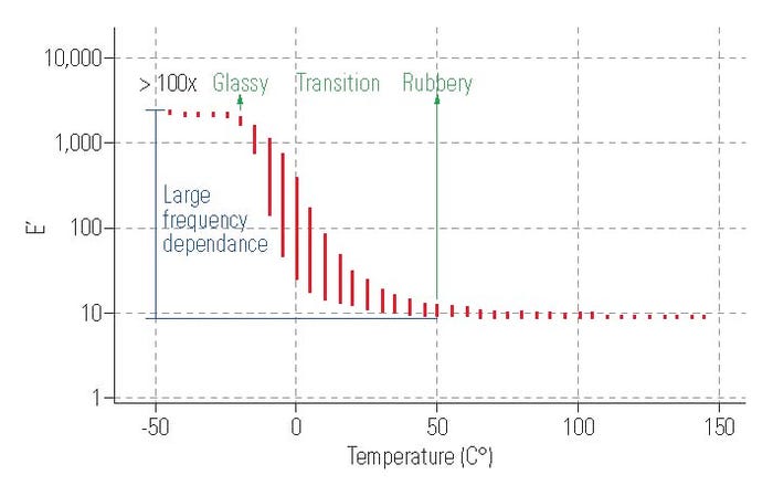
Rubber is highly stretchable, flexible, and resilient. The combination of these elastic properties distinguishes rubber from other types of materials and renders it one of the best material choices for many elastomer components of medical devices. This is especially true for silicone rubber. However, rubber materials are not 100% elastic because they can develop compression set and force decay (stress relaxation), which would cause eventual performance degradation and shorten usage life. Rubber’s mechanical and physical properties also vary dramatically with temperature as it approaches its glass transition temperature, expressed as Tg. Figure 3 shows the storage modulus (which describes dynamic elasticity), E’, measured from a multiple-frequency and multiple-temperature DMA (dynamic mechanical analyzer) test. It can be seen that E’ increases more than 100 times when the rubber material changes from rubbery state to glassy state and that the frequency (or time) dependence of E’ increases significantly during the transition, which is an indication of the loss resilience of the rubber.
|
Figure 3. Rubber storage modulus versus temperature and strain frequency. (Note: The red vertical bars represent the variation of E' at a given temperature but under five strain frequencies varying from 0.01 to 100 Hz. |
It is clear, therefore, that rubber in general should be modeled as a viscoelastic material. The elastic part of the model describes its resilience as a nonlinear function of strain, while the viscous part describes its frequency or time-dependent properties such as stress relaxation. However, because rubber products are used mostly in the rubbery state where viscous effect is negligible, nonlinear and pure elastic hyperelastic models have been developed. These models are commonly used in FEA for rubber products. The most widely used are the Mooney-Rivlin and Ogden models. Engineers should keep in mind, however, that the models are only capable of describing rubber elasticity in a fully relaxed or thermal equilibrium state. For this reason, the hyperelastic models are only applicable in a temperature range that is well above the rubber glass transition temperature, Tg. It should also be noted that the models cannot be used for analyzing certain applications of rubber products. Such applications include vibration damping and impact protection in which viscous energy dissipation plays a major role.
Material Testing and? Characterization
One challenging issue with using the hyperelastic models is determining how to test and characterize a rubber material. Many different test modes such as tension, compression, shear, and bending (flexure) tests have already been designed and are used in material characterization. When a material is considered to behave as a linear elastic material, then simple tension is the test mode commonly used, from which Young’s Modulus, E, is determined directly from the measured stress-strain curve. Other test modes can be employed as well. For example, a shear test can yield shear modulus, G, which in turn can be used to calculate Young’s Modulus by the simple relationship; E = 2*G*(1+v), where v denotes Poisson’s ratio. Most notably, the linear elastic model built on a single test mode is valid for three-dimensional linear FEA.
This simplicity with linear material modeling and characterization, however, does not exist for the hyperelastic modeling of rubber materials. Experience indicates that it’s better to perform material characterization testing in more than one test mode, and then curve fit the stress-strain data from all test modes to generate the material model constants. Usually, considering the cost of testing and the difficulty associated with the curve fitting, engineers in the FEA community often choose two to three modes out of the possible four: simple tension, simple compression, (equal) biaxial tension, and planar shear.
What test modes should one choose? This, in fact, is still a question under much debate. In the authors’ opinion, one basic engineering rule should apply: always design and perform tests that most closely mimic the actual application conditions that the finished component or device will experience.
|
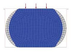
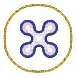
Figure 4. The majority of an installed O-ring body (blue portion) is under a compressive stress state. |
In actual applications, rubber products are typically under three-dimensional strain. In each of the test modes listed above, the rubber test specimens are in one of the simple strain states. We should, therefore, look at which of these strains is the dominant strain in the deformed rubber product. For example, in an installed rubber seal, the majority of the seal body is under compression (as shown in Figure 4 for an O-ring). Obviously, a simple compression test should be included as one of the test modes for its material characterization. Based on this understanding, we do both simple tension and simple compression tests, and we have verified that this two-mode test combination is sufficiently effective for analysis of most sealing applications. However, if an FEA is required for the design of a rubber balloon or an expandable tube, as shown in Figure 5, a biaxial tension test is generally required. If an FEA is required for a rubber coupling that transfers rotational momentum in a clutch, a shear test becomes necessary because the coupling is mainly under twist or shear.
There is an additional test mode for measuring rubber bulk modulus, K, which is a material constant that describes material volumetric compressibility. This test is only needed when rubber products are subjected to confined high-pressure compression, which is rare for medical device applications.
|
Figure 5. The wall of the tube is stretched by internal pressure. |
In general, rubber materials are considered nearly incompressible, simply because their volume change is negligible for most applications as a result of that their bulk modulus (in the order of 105 psi) being several orders larger than their shear modulus (in the order of 102 psi). A rubber material is actually much more compressible than a metal in a confined state (the bulk modulus of typical steel is in the order of 107 psi). This understanding is very important to the design considerations of elastomeric products, especially when thermal expansion, limited groove space, or compression of high-aspect-ratio parts are involved.
Simulation Accuracy and? Relativity
Many factors affect the accuracy and reliability of FEA results such as material modeling, geometry simplification, and numerical methods. However, in nonlinear FEA for rubber products, deviations come largely from material modeling. As discussed above, rubber modeling involves inherent errors associated with the assumptions made with the theoretical models, material testing, and material constant determination. It is also well known that the batch-to-batch variations in mechanical and physical properties of rubber compound are usually significant. It is, therefore, unrealistic to expect that FEA will lead to absolute accuracy in every instance. In fact, without an intensive correlation effort, there is often a lack of direct match between simulated results and actual test results.
|
|
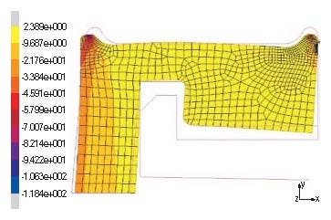
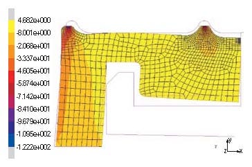
Figure 6. In the graph on the left, the secondary sealing bead is located at the edge (a) of the seal body (axisymmetric model), whereas on the right the secondary sealing bead is moved away from the edge (b). |
This limitation should not, however, prevent FEA from being a highly effective tool for engineers. FEA is mostly used in design iterations for which relative comparison is sufficient in the majority of instances. When analysis results are interpreted in a relative sense, different design ideas, options, or modifications can be compared effectively and accurately and most importantly, rapidly. Furthermore, some tested cases may already exist and can be used as references. For example, shown in Figure 6 are two design options for a molded rubber seal of a medical device. What is their relative performance in terms of sealing and required sealing force? By using FEA, engineers were able to provide a quick answer to this question. Because the design (a) was tested already, the sealing force and other design features of the design (b) can be readily predicted. Using FEA avoided a costly and time-consuming prototyping process and helped their customer to accelerate the device development.
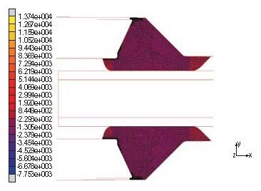
Another example is the design of a rubber gasket for a fluid-delivery device. The gasket functions as a seal as well as a holder of an inserted tube. The initial design was found to have performance problems. Using FEA, engineers were able to identify excess rubber intrusion into the gaps as illustrated in Figure 7(a). Through a rapid series of design iterations, they were able to come up with a robust design solution as shown in Figure 7(b).
Conclusion
|
|
Figure 7. The initial design ([a]; axisymmetric model and the optimized design (b). |
Clearly, FEA is a powerful tool for the development of rubber components for medical devices. However, as emphasized in this article, a good understanding of rubber materials and related modeling techniques are essential to take advantage of this powerful tool. The proper use of FEA can greatly improve both the speed and the quality of product design as well as reduce the overall cost. The discussion on a hyperelastic model based FEA is just a start. Other related topics such as viscoelastic analysis and material characterization challenges are important but beyond the scope of this article.
Kai Zhang is CAE manager, Seal Products Group, for Parker Hannifin Corp. (Cleveland). Shu Peng is engineering manager, Medical Systems Division, for the company.
About the Author(s)
You May Also Like
