ITE Power Supplies and Medical Equipment
Medical Device & Diagnostic Industry MagazineMDDI Article IndexOriginally Published February 2000COVER STORYThere are potential pitfalls in using ITE power supplies in medical devices. Knowing applicable standards will help you avoid mistakes.
February 1, 2000
Medical Device & Diagnostic Industry Magazine
MDDI Article Index
Originally Published February 2000
There are potential pitfalls in using ITE power supplies in medical devices. Knowing applicable standards will help you avoid mistakes.
A large OEM power-supply industry has sprung up to meet the voracious appetite of the information technology equipment (ITE) market for global, high-volume, reliable, cost-effective power supplies. These OEM power supplies are a tempting option for medical equipment manufacturers as well. However, medical equipment regulatory requirements must also be met—a crucial design factor that demands caution when one considers an off-the-shelf ITE power supply for a new device.
In general, ITE and medical equipment share connections to supply mains and the provision for input/output data connections. In both cases, it's anticipated that users or operators will have access to equipment surfaces, and sometimes to data circuits. The primary hazard associated with this type of access is electrical shock. The power supply plays a fundamental role in protecting against this hazard.
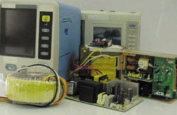 Although ITE and medical equipment share a fundamental approach to protection against electric shock, safety requirements differ.
The primary and obvious difference between ITE and medical equipment is that medical equipment is intended to diagnose, treat, or monitor a patient. Therefore, medical equipment normally comes in intentional contact with the patient: equipment surfaces within the patient vicinity can be contacted by the patient, or contacted by an operator who is also contacting the patient. As patients can be unconscious, connected to multiple equipment, or have open skin regions, the risk of electric shock can be great. Again, power supplies play an important role in protecting against an electric shock hazard in such settings.
The intent of this article is to:
Examine the safety requirements for ITE and medical equipment.
Compare their fundamental approaches to protection against electric shock.
Identify areas in which ITE power supplies may require further evaluation.
Examine some available options.
Outline ideal safety specifications for medical power supplies.
SAFETY REQUIREMENTS
Information Technology Equipment. Most major world markets require IT equipment to provide reasonable protection against injury for users and damage to property. In the United States, regulations from OSHA and FCC must be met. In Europe, the Low Voltage Directive and the Electromagnetic Compatibility (EMC) Directive must be satisfied. Compliance with the international safety standard, Safety of Information Technology Equipment, IEC 60950, 3rd edition (1999-04), is the generally accepted way to satisfy the safety requirements of markets around the world. Additional regulations exist for EMC. (EMC requirements are outside the scope of this article. However, the internationally accepted standards that largely satisfy global regulations are based on CISPR 22 and CISPR 24.)
Within each national or regional market, the international standard must be considered together with any published deviations that take into account local installation codes and expectations of safety. In the United States and Canada, national deviations are contained in the binational standard, CSA C22.2 No. 950-95/UL 1950, 3rd edition (1995-07). This standard is based on IEC 60950, 2nd edition (1991) + Amendment 1 (1992-02) + Amendment 2 (1993-06) + Amendment 3 (1995-01) + Amendment 4 (1996-07). UL and CSA are planning to issue an updated binational standard, based on IEC 60950, 3rd edition, by the first half of 2000. In Europe, regional deviations are contained in EN 60950 (1992) + Amendment 1 (1993) + Amendment 2 (1993) + Amendment 3 (1995) + Amendment 4 (1997) + Amendment 11 (1997).
Medical Equipment. Most major world markets regulate medical equipment. In the United States, the Federal Food, Drug, and Cosmetic Act (and succeeding acts) requires that all medical devices be "safe and effective," and FDA recognizes consensus standards as a means to support a declaration of conformity (new 510(k) paradigm, "abbreviated 510(k)"). FDA lists IEC 60601 + national deviations (UL 2601-1) as a recognized consensus standard. In Europe, the Medical Devices Directive (93/42/EEC, Article 3) requires medical devices to meet the "essential requirements." Compliance is presumed by conformity to the harmonized standards in the Official Journal of the EC (93/42/EEC, Article 5). IEC 60601 + regional deviations (EN 60601) is a harmonized standard. Similarly, IEC 60601 forms the basis for national medical equipment safety standards in many countries, including Japan, Canada, Brazil, Australia, and South Korea.
IEC 60601 is a series of standards. The basic standard containing the core safety requirements for all electrical medical equipment is Medical Electrical Equipment—Part 1 General Requirements for Safety, IEC 60601-1, 2nd edition, (1988-12) + Amendment 1 (1991-11) + Amendment 2 (1995-03). There are collateral (horizontal) standards, which supplement the core requirements by providing technology-related safety requirements. The naming convention for collateral standards is IEC 60601-1-xx. Technologies addressed by collateral standards include medical systems, EMC, x-ray radiation, and programmable systems. There are also particular (vertical) standards, which supplement the core requirements by providing device-specific safety and performance requirements. The naming convention for particular safety standards is IEC 60601-2-xx. Specific devices addressed by particular standards include RF surgical devices, ECG monitors, infusion pumps, and hospital beds. There are approximately 40 Part 2 standards. Although most of these also include essential performance requirements, the trend is to move to another (-3-xx) series of standards for essential performance.
Within each national or regional market, the international standard must be considered together with any published deviations that take into account local installation codes and expectations of safety. In the United States, the national deviations to the core safety requirements are contained in the standard UL 2601-1 (1997-10). In Europe, regional deviations to the core safety requirements are contained in EN 60601-1 (1991-01) + Amendment 1 (1994-06) + Amendment 2 (1996-03) + Amendment 13 (1996-07).
For EMC, the internationally accepted standards that largely satisfy global regulations are in IEC 60601-1-2 (1993-04), and are based on CISPR 11, CISPR 14, and IEC 60801. For some equipment, the FDA reviewer guidance document for premarket notification (510(k)) submissions contains EMC recommendations that are not entirely represented by IEC 60601-1-2.
Since the United States and European markets are the largest ones for medical equipment manufacturers, only the national and regional standards relevant to those markets were cited above. The remainder of this article addresses the generic IEC 60950 and IEC 60601-1 requirements. All references are to IEC 60950, 3rd edition (1999-04) and IEC 60601-1, 2nd edition (1988-12), including all amendments. U. S. and European deviations do not amend the requirements referenced below.
COMMON SAFETY PHILOSOPHY
When designing a product to provide reasonable protection against injury and property damage, how safe is safe enough? This is the question that safety standards address. IEC standards are consensus documents, which define the minimum design requirements.
As technology advances, device usage evolves, and other factors change, a standard can become out of date and its requirements no longer appropriate. Thus, the use of standards does not preclude the need to conduct a risk analysis on products.
Two Levels of Protection. According to IEC 60950, Sub-clause 1.3.1, "Equipment shall be so designed and constructed that, under all conditions of normal use and under a likely fault condition, it protects against risk of personal injury from electric shock and other hazards, and against serious fire originating in the equipment, within the meaning of this standard." ITE must be "safe" in normal and likely fault condition. There are a number of ways to meet this fail-safe requirement, the most common of which is to design in a backup level of protection. When employing this strategy, it must also be unlikely that the failure of the first means of protection will go undetected or tolerated by the user before a likely fault of the backup protection occurs. To summarize, a common strategy for designing ITE is to design in two levels of protection.
In some situations, however, two levels of protection might not be considered a reasonable level of protection against injury or property damage. For example, developers of safety requirements for aircraft, nuclear power plants, or missions to Mars may have other ideas about what constitutes a reasonable amount of protection. However, the ITE standard defines two levels of protection as sufficient for ITE.
In a similar manner, IEC 60601-1, Clause 3.1 states that "Equipment shall, when transported, stored, installed, operated in normal use, and maintained according to the instructions of the manufacturer, cause no safety hazard which could reasonably be foreseen and which is not connected with its intended application, in normal condition and in single-fault condition." As with ITE, medical equipment must be "safe" in normal and likely fault condition, and a common strategy for designing such equipment is to design in two levels of protection.
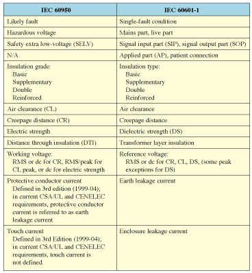
Table I. Correlation of terminology for IEC 60950 and IEC 60601-1.
COMMON TERMINOLOGY
There is generally a one-to-one correlation of IEC 60950 and IEC 60601-1 terminology. Table I summarizes this mapping, and provides the basis to discuss both standards with a common language. In this article, the medical terminology will be used.
PROTECTION AGAINST ELECTRIC SHOCK
At established threshold levels, an electrical current passing through the body can cause electric shock. This current depends on the voltage and the body impedance.
Fundamentally, the basic strategies to limit the accessible current, and therefore protect against electrical shock, are to place high impedance (insulation) in the current path, or limit the accessible voltage (earthing or grounding).
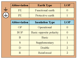 Table II. Levels of protection (LOPs) against electrical shock.
As mentioned previously, both IEC 60950 and IEC 60601-1 require two levels of protection against electrical shock. Both IEC 60950 and IEC 60601-1 define insulation and earthing (grounding) terminology to denote their role with regard to levels of protective provided. Table II summarizes the terminology.

Figure 1. (a) Basic insulation plus protective earthing, (b) basic plus supplementary insulation, and (c) reinforced insulation.
Knowing that the goal is two levels of protection, it becomes clear that the combination of basic insulation and protective earthing satisfies this requirement. If the basic insulation fails, the user has access to a protectively earthed surface. If the protective earthing supply connection is broken, the basic insulation provides separation (high impedance) between the live part and the user. This is illustrated in figure 1a.
Similarly, basic and supplementary insulation will provide two levels of protection. By definition, this is considered double insulation. This scheme is illustrated in figure 1b.
Reinforced insulation is a single system that has been shown to provide the equivalent of two levels of protection, as shown in figure 1c. By definition, it is considered more than a single fault for reinforced insulation to fail.
Looking at the levels of protection provided by the insulation types, one might wonder if two means of basic insulation could be considered as providing two levels of protection. However, basic insulation by definition is not intended to be a backup means of protection. This role is reserved for supplementary insulation (or protective earthing).
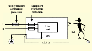 Figure 2. Protective earth (1 LOP).
For earthing to provide a level of protection against electric shock, it's important that the earthing connection have a sufficiently high current-carrying capacity and low impedance. In the event of a failure of basic insulation, the earthing connection must remain intact at least until the branch protection clears (high current), and the accessible surfaces must remain at or near earth potential (low impedance). Figure 2 illustrates this principal. Earthing that has not been evaluated for these properties is by definition functional earthing. Earthing provided for EMC shielding purposes is an example of earthing that may not need to be evaluated as protective earthing.
When considering the suitability of insulation, it's important to consider the voltage stress the insulation is subjected to under normal use, which is defined as the reference voltage. IEC 60601-1, Clause 20.3 specifies, "For insulation between two isolated parts or between an isolated part and an earthed part, the reference voltage (U) is equal to the arithmetic sum of the highest voltages between any two points within both parts." In the case in which both parts share a common earth reference, the reference voltage is the higher of the voltage in either of the two parts. With IEC 60950, these same requirements must be considered as well as voltage peak values. In the case of switching power supplies, repetitive peak voltages are common. (The consequence this can have on air clearances required by IEC 60950 is presented in more detail when air clearances are discussed below.)
Insulation diagrams (sometimes called isolation diagrams) are used in product design to graphically:
Identify insulation types, reference voltages, and earthing types.
Determine required creepage, clearance, and transformer-layer insulation thickness (physical requirements).
Determine required dielectric-strength values (test requirement).
Identify alternative constructions.
Convey design criteria to purchasing staff, vendors, and others.
Figure 3 illustrates a simple insulation diagram for a product with a supply mains connection, a protectively earthed (PE) enclosure, and a SIP/SOP (ITE SELV) data connection. The mains circuit is considered a mains part (MP); the SIP/SOP circuit is considered a live part (LP). Bridging the mains part and the live part is the power supply (P/S). Shown is an insulation and earthing scheme that provides two levels of protection against electric shock: from MP to PE is basic insulation, and from MP to LP is double or reinforced insulation. The SIP/SOP is tied to earth (FE), as is common with ITE. This is acceptable in medical equipment in cases when separation requirements in IEC 60601-1 Clause 17(g)2 and accessibility requirements in Clause 16(a)5 or 16(e) are met. Since the SIP/SOP is connected to functional earth, the reference voltage from mains part to SIP/SOP is the mains voltage.
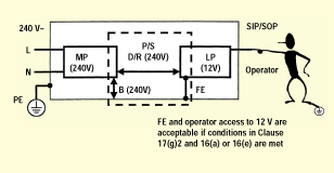 Figure 3. Insulation diagram for a typical medical product (neglecting AP).
POSSIBLE PITFALLS USING ITE POWER SUPPLIES
Knowing which insulation types, reference voltages, and earthing types are required by a product design has physical construction and test consequences. Insulation types are evaluated by examining physical distances (creepage and clearance) and, in some cases, checking insulation thicknesses (transformer layer insulation). Insulation materials provided in lieu of physical air separation are tested for dielectric strength. All distances and insulation thicknesses are evaluated with leakage current measurements. The following section examines each of the insulation requirements in more detail.
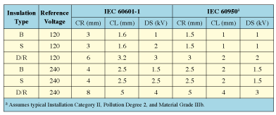
Table III. Comparison of creepage, clearance, and dielectric-strength requirements.
Creepage and Clearance. Taking the insulation types and reference voltages determined as necessary in the simple insulation diagram, we can look up the creepage and clearance distance requirements. IEC 60601-1 specifies creepage and clearance requirements in Clause 57.10. Table III shows these distances for both medical equipment (IEC 60601-1) and ITE (IEC 60950). For ITE, we've assumed typical Installation Category II, Pollution Degree 2, and Material Group IIIb. Air-clearance requirements specified by IEC 60950 include a component dependent on maximum repetitive peak voltages, whereas air clearances specified by IEC 60601-1 do not. Repetitive peak voltages are common in switching power supplies. Table III assumes that any repetitive peak voltages do not exceed 420 V. Should repetitive peak voltages exceed 420 V—and this is possible with today's switching power supplies—repetitive peak voltages of 787 V must be present before the clearance requirement of IEC 60950 equals the 5-mm requirement of IEC 60601-1. Repetitive peak voltages higher than 787 V are rare in today's switching power supplies.
As shown in Table III, in all cases creepage and clearance distances required by IEC 60601-1 are greater than those required by IEC 60950. This does not mean that ITE power supplies are unacceptable in all medical devices, but rather they have not been validated as complying with IEC 60601-1. The medical device manufacturer must do this validation.
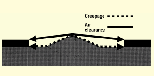 Figure 4. Creepage and air clearance distances.
First, let's review what creepage and clearance distances are. Creepage distance (CR) is the shortest path along the surface of insulating material between two conductive parts (sometimes called over-surface spacing), while air-clearance distance (CL) is the shortest path in air between two conductive parts (sometimes called through-air spacing). Creepage and clearance are illustrated in figure 4.
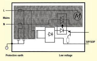 Figure 5. Circuit blocks.
Next, let's review how the circuit blocks of the insulation diagram map to an actual product. Consider the product represented by the schematic in figure 5. This is a product with a mains-connected motor. There is a mains-connected transformer that supplies low-voltage secondary power for control circuitry. The SIP/SIP connection might be for a foot-switch control that activates the solid-state relay and therefore the motor. The product could be, for example, a smoke-evacuation device used to assist with RF surgical procedures.
Notice that there is a single mains part circuit block, a protectively earthed enclosure, and a SIP/SOP circuit block, mapping exactly what is illustrated in figure 3. The primary advantage to insulation diagrams is that they provide a layer of abstraction above the details of the product and allow one to focus on the insulation and earthing requirements.
When considering whether the required basic insulation requirements from mains to earth are met for the smoke-evacuator example shown in figure 5, it's clear we need to consider such components as an appliance inlet, fuse holders, Y capacitors, transformer (core-earthed), motor (enclosure-earthed), printed wiring board, and wire insulation. To verify the required double- or reinforced-insulation requirements from mains to SIP/SOP for the same device, we must consider such components as the transformer, opto-coupler, relay, printed wiring board, and wire insulation.
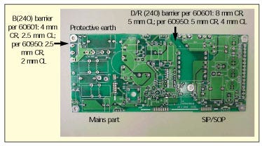 Figure 6. Printed wiring board example.
Figure 6 illustrates exactly what creepage measurements are needed in order to validate that the requirements are met. With the components mounted on the board, clearance distances will need to be measured. If this printed wiring board was designed to meet the minimum requirements of IEC 60950, the required IEC 60601-1 distances may not be provided.
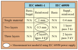 Table IV. Comparison of transformer layer insulation requirements.
Transformer Layer Insulation. The transformer layer insulation requirements for medical equipment can be found in IEC 60601-1, Clause 57.9.4e. Table IV shows the transformer layer insulation requirements for medical equipment alongside the solid insulation requirements for ITE (IEC 60950). As can be seen in the table, for reinforced insulation the IEC 60601-1 transformer layer insulation requirements are not represented by IEC 60950 requirements. The medical device manufacturer must validate that the transformer meets IEC 60601-1 requirements and not the minimum requirements of IEC 60950.
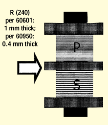 Figure 7. Cross section of transformer layer insulation, showing a bobbin with insulating partition.
As an example, let's consider two common transformer constructions. The first is a transformer with a center flange bobbin, which is common for linear transformers. A cross-sectional view of such a transformer is shown in figure 7. For a medical device, the thickness of the center flange must be a minimum of 1 mm (single material).
The second construction is a concentrically wound transformer, which is common in switching power supplies; figure 8 shows cross-sectional views from the top and side. We must validate that the insulation material between primary (mains) and secondary (SIP/SIP) windings meet the transformer layer requirements. Because two layers of insulating material will normally be less than 0.3 mm, this typically requires validating that at least three layers of insulating material are provided.
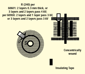 Figure 8. Transformer layer insulation, showing a bobbin with insulating tape.
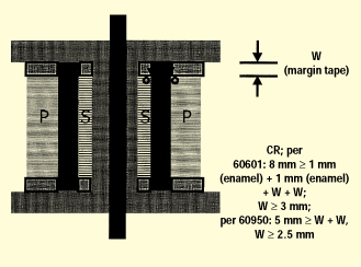 Figure 9. Transformer creepage, showing a bobbin with insulating tape.
The concentrically wound transformer provides an excellent example of an important creepage distance that must be considered. Figure 9 shows where the primary-to-secondary insulation butts up against the bobbin end flanges. This joint is considered an uncemented joint, and the distance between primary and secondary end turns needs to meet the creepage distance requirements, with one special allowance in that the enamel coating on the primary and secondary windings contributes 1 mm each towards the required creepage distance. Shown in figure 9 is a margin tape of width W, which provides positive end-turn retention and maintains the minimum required creepage distance. For IEC 60601-1, the width W will need to be at least 3 mm in order to meet an 8-mm creepage distance requirement after taking into account the 2-mm contribution of the enameled windings. For IEC 60950, W will need to be at least 2.5 mm to meet a 5-mm requirement, since for IEC 60950 the enamel on windings contributes nothing to creepage distances. In addition, creepage distances from winding end turns to opposite winding exit leads must be considered.
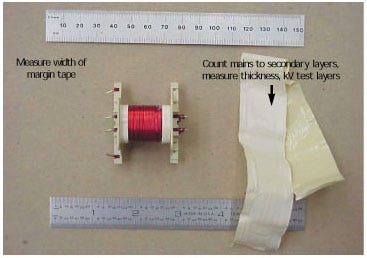
Figure 10. Example of a concentrically wound transformer.
Figure 10 illustrates a concentrically wound transformer and the type of disassembly and activities that are needed in order to validate that the transformer's construction complies with insulation requirements.
You May Also Like

