When x-ray inspection is used as part of a quality assurance program for any assembled device, steps must be taken early in the design stage to anticipate its use later in the development and production processes. Electronic assembly manufacturers learned this lesson years ago, and medical device manufacturers are now discovering it.
July 18, 2011
Just as radiologists must know human anatomy thoroughly before they can interpret a radiograph, so must medical device manufacturers understand the nature of their devices’ constituent parts and how these parts interact with the x-ray inspection process. For example, some manufacturers of molded catheter hubs have found that without a clear x-ray image, internal voids and defects in the hub that could harbor blood clots would not be detected. The polymers used for these moldings can exhibit very low x-ray opacity, making detection difficult.
There are several steps involved in learning how to interpret x-ray images and design for x-ray inspection. First, manufacturers need to understand the nature of the x-ray shadow and its modalities. Then, they need to see how medical device developers and manufacturers are using x-ray inspection. Finally, they must consider taking measures early in the design process to ensure a clear, accurate image when the assembled device undergoes x-ray inspection.
X-ray Shadow
The x-ray image is basically a shadow image of the object, projecting a 2-D representation of shape, opacity, and thickness. Many different 3-D configurations can project similar 2-D shadows, and the relative position of components within the object affects the size and appearance of the x-ray shadow.
|
Figure 1. |
Characteristically, the shadow is distorted by geometric magnification, which causes details of the object closer to the x-ray source to be magnified to a greater degree than details farther from the source. The magnification of the x-ray image can be calculated as the ratio of the distance from the x-ray source to the shadow plane divided by the distance from the source to the object (see Figure 1).
As long as the object has a finite thickness, the x-ray image cannot have true dimensional accuracy. As the object becomes magnified, it loses edge sharpness. This is the penumbra effect, which results from the finite size of the x-ray source (see Figure 2).
|
Figure 2. |
X-ray Imaging Modalities
For viewing, the x-ray shadow can either be exposed to a photographic film or converted to a video image. Different devices are used to convert the x-ray image to a video or fluoroscopic image. Thomas Edison invented the first fluoroscope in 1896, when he discovered that calcium tungstate acted as a scintillator and fluoresced when exposed to x-rays. He had intended to use x-ray–excited fluorescence as the basis for a light source, but the technician working on it, Clarence Dally, developed terminal cancer. The technology has since progressed.
Today, the two basic fluoroscopic modalities can be described as static imaging and dynamic imaging. Both depend on a scintillator to convert the x-ray image to a light image. The flat panel imager is basically a scintillator coated onto a CCD array that produces static fluoroscopic images (see Figure 3) or a series of still x-ray images.
|
Figure 3. |
Dynamic, or real-time, fluoroscopy produces x-ray movies. Dynamic imaging fluoroscopes employ a scintillator coupled with an image-intensifying device that amplifies the light image and presents it to a video camera for display (see Figure 4). The image-intensifying device can be a demagnifying type (Figure 4) or a nondemagnifying type.
Magnification fluoroscopy employs fine-particle, high-resolution scintillators coupled to nondemagnifying intensifiers that produce high-resolution fluoroscopic images at relatively low radiation dose levels. These fluoroscopic images can then be magnified optically for video display. Magnification fluoroscopy is increasingly being used in preclinical studies of medical devices using small animal models. Other imaging modalities include computerized radiography, wherein the x-ray image is stored on a storage phosphor and read out with a laser, and computerized tomography (CT), wherein the image is mathematically reconstructed from many measurements of the transmission value of a pencil beam of x-rays.
|
Figure 4. |
X-ray Inspection in Device Manufacturing
In the most obvious application, x-ray inspection is used to detect the presence or absence of catheter and stent radio markers, even after packaging. Increasingly, injection molders are also using x-ray inspection as a quality assurance instrument in the development and production of molded medical components. For catheter hubs, x-ray inspection is ensuring that lumens are properly seated and that there are no voids. Even in the molding of polyetheretherketone (PEEK) implants, which are formulated to exhibit x-ray transparency, sensitive x-ray imaging technology can detect voids. In the manufacture of surgical staples, x-ray inspection ensures that all staples are present after packaging and surgical trays are complete. In the development of stents, high-resolution magnification fluoroscopy permits the observation and fluoroscopic video recording of the stent deployment as an x-ray movie. Additionally, x-ray detection can detect stent wire breaks following fatigue testing. The stent can be observed with dynamic fluoroscopy as it slowly rotates, allowing the complete wire structure to be inspected.
FDA addresses the radiopacity of stents in a document titled Non-Clinical Tests and Recommended Labeling for Intravascular Stents and Associated Delivery Systems. The document recommends that the manufacturer evaluate the radiopacity of a stent at its smallest diameter and shortest length during the stages of delivery and deployment (if separate from delivery), and after implantation. Stent visibility by fluoroscopic imaging ensures proper placement and allows follow-up and secondary treatment. The document recommends the qualitative or quantitative indication of the fluoroscopic visibility of the stent.
High-resolution magnification fluoroscopy has also contributed to the research and development of vena cava filters. In the laboratory, researchers are able to observe and video the action of a filter design in snaring simulated blood clots in an excised pig’s vena cava.
X-ray inspection has contributed even more significantly to the manufacture and quality assurance of implantable devices such as pacemakers, defibrillators, and batteries. New, high-resolution magnification fluoroscopic technology can detect wire breaks and tenuous electrical attachment.
Designing for X-ray Fluoroscopic Inspection
When anticipating the use of real-time x-ray systems in the development and quality assurance of medical devices, a number of factors need to be considered. Primary among them is x-ray opacity, or radiopacity.
Different materials have different radiopacities. It is important to note that an object of high radiopacity can veil the details of an object of low radiopacity, regardless of which object is in front.
Figure 5. |
As an example of designing for x-ray inspection of devices used in angiographic procedures, consider stent development. In Figure 5, the difference in radiopacity is evident in the fluoroscopic images of nitinol (nickel-titanium) and stainless steel stents in a preserved rat. The nitinol stent on the left has visibly less radiopacity than the stainless steel stent on the right. To be detectable via fluoroscopy, the nitinol stent must have platinum markers on the tips. Because radiopacity is a function of the atomic weight of the device’s constituent elements, the platinum tips—having higher atomic weight—add radiopacity.
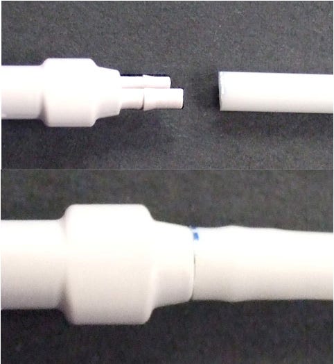
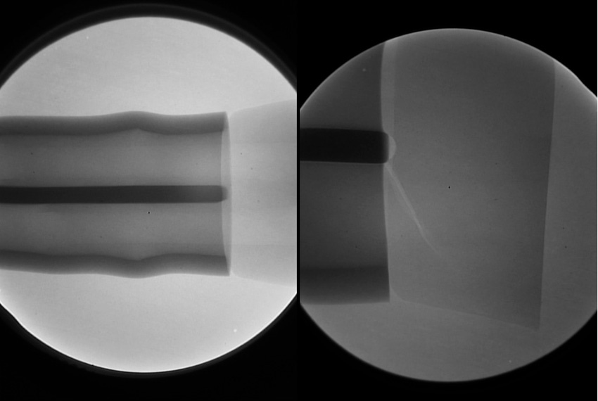
In a case study, a medical device consisted of a flexible tube on the left and a molded connector on the right; the tube was intended to be assembled to the connector (see Figure 6). On assembly, visual inspection revealed cracks in the connector prongs. The tubing had been radiopacified and the connector had not. After assembly, the higher opacity tube obscures the cracks in the lower opacity connector prongs (see Figure 7).
|
Figure 6. |
The relative radiopacity of a material can be anticipated by the atomic weight of the constituent elements of that material. Barium and bismuth have atomic weights close to lead and tungsten, accounting for their high radiopacity. Therefore, the radiopacity of a polymer can be enhanced with inert additives such as barium sulfate or bismuth trioxide.
Figure 7. |
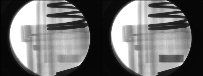
For example, in the design of a critical drug delivery device, it was found that an internal, moving plastic component needed to be x-ray inspected carefully as part of a quality assurance program. At an early stage of development, opacifying the polymer was considered and implemented successfully. The difference is shown in Figure 8.
In orthopedic research, magnification fluoroscopy has helped advance understanding of the effects of mechanical load on the healing between tendon and bone in studies using rat models.
|
Figure 8. |
Radiation Levels Employed in X-ray Inspection
Would the level of ionizing radiation being employed in x-ray inspection damage the device? To address this, we have to look at relative levels of radiation.
A number of units are used to express dose levels. Here, we will use the milliRem (mRem). For the inspection of a medical device, the dose rate could be from 200 to 1000 mRem per minute.
NASA studied extensively the potential for radiation damage to vulnerable electronic components in space. The relatively vulnerable Si MOS Linear IC products might show damage at approximately 400,000 mRem and will likely degrade or fail beyond 1 million mRem. Regarding radiation sterilization and plastics, the current state of the art in formulating radiation-stabilized PP for molded parts (syringes) is usually limited to less than 5 million mRem. Thus, it is improbable that x-ray inspection of medical devices would degrade the structure in any way.
Conclusion
X-ray inspection and high-resolution magnification fluoroscopy are being used increasingly in the development and manufacture of medical devices and preclinical study of those devices. However, the factors affecting the x-ray shadow are not always clearly understood by users, which can lead to misinterpretation of the x-ray image. By learning how to design for, interpret, and use x-ray inspection, in addition to other quality assurance instrumentation, medical device manufacturers can demonstrate their commitment to good manufacturing practices.
Gil Zweig is president of Glenbrook Technologies (Randolph, NJ).
About the Author(s)
You May Also Like


