Anatomy of R&D: Incorporating Load-Cell Sensors into fMRI
Originally Published MDDI May 2006 SENSORSWhen two research facilities focused on improving functional MRI to aid patients with brain trauma, both found success in different ways. Their results reveal novel ways to use load-cell sensors with magnetic resonance imaging. Julius P. A. Dewald and Joseph Hidler
SENSORS
|
For Northwestern's setup, a wooden frame surrounds the subject on the MRI table. The load-cell sensor is mounted to the wood frame. The interface is bound to the fiberglass cast on the subject's forearm, wrist, and fingers. |
Magnetic resonance imaging (MRI) is a system that can provide a photographic image of the brain with a resolution of less than 0.5 mm. Structures hidden deep within the center of the brain can be viewed. However, even though basic MRI provides detailed information regarding brain structure, it tells nothing of actual brain functions.
Functional MRI (fMRI) was first introduced in 1992. It allows users to watch the human brain in action, revealing visual images of the changes underlying a broad range of brain functions, including hearing, sight, feeling, movement, and creation of memories. Increased blood flow to the activated areas of the brain appears on fMRI scans as the process happens. The technology provides a way to view the neural changes that occur behind behavior, rather than only showing the consequences of these effects, as with that of a standard MRI.
The areas responsible for specific senses are localized, thereby identifying the brain regions that become more active during individual task performance. An MRI can be used to see how the brains of healthy subjects learn new tasks and how those with brain trauma, such as stroke, improve over time.
For example, fMRI monitoring indicates that the pattern of brain activation associated with a simple hand movement changes after a stroke that causes limb weakness. As an adaptive response to the injury, movement of an affected hand requires both sides of the brain, rather than just the opposite side of the brain. Similar results have been seen in patients with multiple sclerosis and physical brain trauma.
However, unlike physically passive studies of vision and hearing, physically active scanning has been problematic. To get usable images, the head of the subject in the fMRI must remain absolutely still. Any movement causes a bad image. Even with usable images, most active fMRI data have been extremely subjective and prone to error. It is difficult to measure exactly how much movement occurs, what the stress or torque level actually is, or how it changes over time.
Two research facilities have taken fMRI a step further, creating accurate systems for physical function scanning. The Department of Physical Medicine, Rehabilitation, and Biomedical Engineering at Northwestern University (Chicago), and the National Rehabilitation Hospital in Washington, DC, have both developed improvements to fMRI. The goal of each system was to measure actual muscle and brain changes during muscle movement. Doing so reveals how, and in which specific area, brain activity changes, improves, or reconstructs itself in subjects over a period of rehabilitation.
|
Examples of the load-cell sensors from which JR3 Inc. (Woodland, CA) developed magnetic-compatible versions. |
The researchers hope to provide better understanding of exactly how the brain can recover after trauma to enable manufacturers to develop better rehabilitation methods using load-cell sensors. To understand the challenges, a brief overview of the mechanics of magnetic resonance is required. Although certainly not complete, this provides a good review of the concerns that must be met when introducing any new instrumentation into a working MRI situation.
Mechanics. The core of an MRI machine is a supercooled (–270°C) magnet over 50,000 times more powerful than the earth's magnetic field, which is typically 1.5–3 T.
Within the magnet are many types of gradient imaging coils. Volume coils surround the imaged object while surface coils are placed adjacent to the imaged object; an antenna (i.e., receiver coil) is placed directly around the subject's head. Some coils can operate as both transmitter and receiver. Other coils are designed as only receivers of the radio-frequency (RF) signal.
The subject is positioned within the magnet tunnel (or bore) by a computer-controlled patient table with a positioning accuracy of 1 mm. An RF shield surrounds the scan room. The shield prevents the high-power RF pulses from radiating out through the hospital or research facility. It also prevents the various RF signals of television and radio stations from being detected by the imager. Some scan rooms are also surrounded by a magnetic shield, which keeps the magnetic field from extending too far into the facility. In newer magnets, the shield is an integral part of the magnet.
Potential Problems. Although an MRI does not use ionizing radiation to produce images, there are still some important safety considerations to note. These concern the use of strong magnetic fields and RF energy. Because of the magnetic field, it is imperative that no ferrous metals come into the MRI room. The magnetic field immediately pulls these types of materials into itself, which can injure or kill an individual in the magnet. It can also seriously damage the magnet and imaging coils.
Subjects with many types of surgical implants, metal fillings, shrapnel, or ferromagnetic clips or pins in their bodies cannot be imaged. These objects would be twisted and pulled into the magnetic field, causing serious injuries.
Burns and noise levels are also of concern. Some RF coils, such as surface coils, have failure modes that can cause burns, so it is important that no body parts touch the wall of a body coil being operated in transmit mode with a surface coil as the receiver. An imaging session creates a series of repetitive loud knocking sounds when the magnetic field gradients are turned on and off. Because of the volume of these sounds, subjects must wear ear protection that provides upwards of 26 dB of noise suppression.
Understanding Rehabilitation in Brain Trauma
Researchers have begun using load-cell sensors in conjunction with fMRI to study the muscle-brain connection of patients who have experienced stroke or head trauma. The results so far have been promising.
Load cells are force transducers. They take many forms and accommodate a range of weighing and measuring applications over virtually every industry, from automotive production-line robotics to intravenous fluid-delivery systems. They are based on either silicon or metal-wire strain gauges etched or bonded to a surface to create a Wheatstone bridge. When stressed, the strain gauge changes form and transmits this change as a signal to a device that converts it from analog to digital for display or readout of the precise torque delivered to the gauge in real time.
|
While in the fMRI scanner, the subject's goal is to move the green circle inside the yellow target area. The green circle turns purple once inside the yellow one, and disappears after 1 second. |
Northwestern University was first to develop a process of combining load-cell sensors and fMRI technology. After working with several industrial suppliers, researchers developed a sensor that could function within the magnetic environment of the MRI with robust and repeatable measurement. Using the sensor, the researchers developed a system that allowed subjects to be directly attached to the load cell and transmit both mechanical signals and brain images to a remote computer simultaneously.
The National Rehabilitation Hospital followed with a similar system using the same nonferrous load-cell sensor developed for Northwestern, but employing a slightly different approach to the mechanics. The systems of both research facilities allow precise reading of brain activity via fMRI. Both systems image and measure upper-limb muscle control. The device developed at Northwestern is focused on the shoulder and arm, using isometric muscle contraction rather than actual arm movement. The system at the National Rehabilitation Hospital is focused on the wrist and hand. It has the subject push and pull a lever that is similar to a joystick.
Before the load cell was incorporated into the Northwestern design, the university monitored subjects' efforts of pushing against an object without measuring anything. This enabled researchers to see whether the fMRI could pick up signals from the brain. Once the researchers were satisfied with this part of the test, they tested the load cell, both inside and outside of the MRI bore, to see whether there was any change in the signal based on proximity to the magnetic field.
|
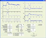
A data collection screen from Northwestern shows the forces (x, y, and z) listed on the left, with through-the-lens pulse train below. Elbow and shoulder torques are on the right. Parameters entered in the text boxes for the subject are located below the plots. |
One of the early tests was simply putting a ruler at the tip of the load cell and moving the ruler so it would vibrate—just to see whether the load cell could quickly handle changes in the mechanical inputs as well as outside the magnetic environment. The load cells were moved to different locations in the magnetic field, and tests were repeated to ensure that the reading was true and consistent in all locations. Only after all tests proved sound were human subjects brought in.
For more than 15 years, Northwestern has been studying how people use their muscles to generate force and torque with arm and shoulder. Ten years ago, Northwestern began using high-accuracy load cells manufactured by JR3 Inc., a sensor manufacturer located in Woodland, CA. The load cells were combined with high-density electroencephalogram (EEG) technology to test the connection between physical force and torque exertions and the brain.
The high-density EEG electrode array used 163 electrodes attached to the subject's head to measure activity in the brain cortex while the subject generated shoulder or elbow torque. EEG recordings suggested that the regions of the brain used for control of individual body functions such as the shoulder versus the elbow, start to reorganize after brain trauma. An increased overlap develops in the brain at the motor cortex between the areas that control the joints of the arm. The team concluded that greater overlap indicates greater loss of independent joint control.
Design and Development. In 2000, Northwestern began a project to see whether a load cell could be developed that would work in the gradient magnetic field of an MRI machine. This is not a natural pairing of technologies because load cells are typically made of ferrous materials. What worked perfectly well in the EEG environment would be a disaster near an MRI. Therefore, a load cell that used silicon strain gauges was tested first. In theory, the silicon gauges should have worked well; but in actual application, the signals were highly distorted. The university went back to the sensor manufacturer to see whether its load cells could be modified for the fMRI environment.
The company had already produced a line of load cells for industrial environments having serious noise problems and strong magnetic fields, such as for use on lines where the sensor is mounted on robotic arc-welding heads. Various space projects for NASA, for which there were significant noise issues, also served as a model for the load cells.
The MRI environment required two sets of changes for the load cells. The first task was to improve noise rejection for MRI and RF signals, as well as improve immunity to interference in the sensor signal that might come from the magnetic field. Second, all potentially magnetic material had to be removed from the sensor. Even materials normally considered nonmagnetic, such as certain types of stainless steel, had to be removed. Steel fasteners, bolts, nuts, and screws were replaced with those made of brass, titanium, or bronze. The type of material used depended on the specific location and the strength needed.
From a specification and capability standpoint, only the packaging was different in these load cells. All standard models could be made MRI compatible. However, even the tiny connector at the end of a cable with only a trace amount of steel had to be removed.
One additional precaution was to ensure that any bits or chips of steel dust did not get onto the sensor as it was brought into the magnet. Even if these bits were too small to do any harm, they could distort the image.
Once a suitable sensor was built, the Northwestern team began its first experiments. Those first sensors fit the criteria, but the RF pulses from the MRI machine caused problems with the signal picked up from the load cell. Little voltages out of the load cell initially looked good and showed what the individual was doing, but placed in the large magnetic field, the RF pulses created huge spikes in the signals. Any electrical signal coming out of that environment was likely to be compromised by big RF pulses.
The Northwestern team experimented with forms of filtering to eliminate the signal spikes. They found that the spikes occurred at a special frequency and time. Therefore, the team developed a filter to remove those areas by using a cutoff frequency lower than the spikes.
On these load cells, the electronics to amplify the signal are usually built in. For this particular application, the electronics were moved to an external box kept in a separate room housing the computers that control the MRI. The analog signals from the load cell were generated, filtered by the custom box, and then translated for analog-to-digital conversion for computer screen display. Because of this filtration segmenting, when a subject generated a shoulder or elbow torque against the load cell, the signal was nearly as clean as those in the experiments outside of the fMRI environment using standard sensors.
|
At the National Rehabilitation Center, subjects are inside the MRI chamber to the waist, with the wrist module inside the scanner bore. |
Because the National Rehabilitation Center used the same load-cell sensor, it did not have to go through the same development process. However, each facility found a different way to construct the system.
Configurations and Capabilities. The two systems were developed independently of each other, so although the goals were the same, each team took a different approach. The Northwestern team configured their load-cell unit in a wooden housing and concentrated on isometrics of the elbow and shoulder. The National Rehabilitation Hospital team had the sensor unit housed in plastic and concentrated on the movement of the hand and wrist. Both developed unique software and filtration to monitor load-cell output and to compare it with the fMRI images.
In the Northwestern design, a subject's elbow is bent at 90°. The head, arm, and shoulders are inside the MRI. The structure has the load cell on one end and the test box on the other side. The load cell is connected to the hand and wrist of the individual to measure isometric or static torques. Subjects do not actually move, but rather goes through a series in which they are contracting their muscles against the load cell.
|
The joystick module, developed by the National Rehabilitation Center, measures wrist exertion. Four padded bumpers inhibit contraction of the proximal arm muscles and support the forearm. The plastic wedge is mounted to a base that the subject lies on to anchor the device. |
A computer with a data-acquisition card picks up the signals from the load cell and shows brain activity simultaneously—whether working at the shoulder or the elbow. It also indicates the direction in which torque is being generated. The computer is connected by a cable to the MRI, but is kept in a separate shielded room. Inside the MRI bore, a mirror projection system positioned above the subject enables the person to see what is happening. The data acquired while the person is pushing or pulling against the load cell is transmitted to the data-acquisition computer in the shielded room.
The key to this system is the exact positioning of the arm. The elbow or finger must not touch the wall of the magnetic bore. It requires very precise placement. A prototype holding fixture is made of wood; however, plastics that offer more flexibility are being considered for the next version of the system.
At the National Rehabilitation Hospital, the subject is also placed inside the fMRI to the waist, with the subject's head in the center of the magnet in the head coil. The arm-sensor device is placed next to the subject, slightly inside the fMRI tunnel. The limbs are supported so that the head will not move when the hand is flexed. A Delrin (acetal resin plastic) handle protrudes from the side of the unit. The handle is attached to one side of the load cell. The other side of the cell is mounted on a polyethylene wedge. The subject's elbow is flexed to 30°.
The wedge is mounted so that the subject's body weight anchors the system and prevents unwanted movement. It also enables a quick setup change for right- and left-arm testing.
A 30-ft cable connects the load cell to an optical isolation panel where the load-cell signals and sensor power are transferred between the control room and MRI room. All analog signals are read into a PC through a custom electronics module containing a 16-bit analog-to-digital convertor. Signals are low-pass filtered at 50 Hz before being sampled at 1000 Hz. Custom software acquires signals from the load cell and displays measured joint movements to the subject in real time for target-matching purposes.
An image of a target graphic is projected to the subject using a color liquid-crystal display projector. The graphic is projected onto stereo glasses affixed to the top of the head coil. The subject can see the results of the test in real time. As with a video game, the subject uses a joystick to move a cursor into a target frame, holds it there for a given amount of time, and then relaxes. Specifics are set to the requirements of each individual being tested.
|
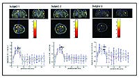
The scan from the National Rehabilitation Center depicts the motor cortex during a wrist flexion behavior task at 20% maximum exertion level. |
Because the nonferrous load cells were developed by the time National Rehabilitation Hospital began its project, the researchers focused their testing on the system as a whole for repeatability. Subjects were tested repeatedly to see whether results remained consistent. It was also important to the researchers that the device be comfortable and easy to use. Subjects reported that it was. If the subject is in any discomfort because of how the body is oriented or how the arm is held in the fixture, this stress can affect all muscles. The tests are designed to show how the brain reacts when specific muscles are used, so comfort is critical. To make the subjects more comfortable, the center tested many people of different body types within the fMRI test apparatus and made adjustments to the design until every subject tested found the device to be comfortable and the test data showed clean scanning readouts. It was found that for both comfort and ease of use, all-plastic-and-fiberglass materials were the most suitable.
Even though the magnetic issue was already addressed, the researchers had to be assured that when placed inside the fMRI, the device would not cause significant noise problems within the brain images. Conversely, they had to reestablish that the environment of the fMRI magnetic field would not interfere with the functionality of the sensor. Neither the noise levels nor the magnetic field proved to be a negative influence on the load cell. The design itself proved robust and accurate and is currently being replicated for use at the University of California, Los Angeles Neurorehabilitation and Research Center.
Conclusion
Standard load cells were first used for measuring limb control and comparison of muscle torque and brain activity with EEG technology. Joining the data from nonferrous load cells to fMRI scanning for in-depth detail of how the brain was reacting offers a substantial breakthrough in understanding brain trauma rehabilitation.
A load-cell-enabled fMRI can track independent improvement in both muscle function and brain activity. The high sensitivity of the load cells and precise measurements of isometric joint movements using neuroimaging studies of motor recovery after brain trauma allow patients with limited motor function to be studied accurately. These precise studies provide data for the development of ever better rehabilitation devices.
The concept of using load-cell sensors in combination with fMRI is gaining wide acceptance. The availability of nonferrous load-cell sensors, combined with fMRI technology and linked via computer, is opening doors for further development of these types of medical systems. Such systems could include neurological systems. What comes next is limited only by the theories, experiments, and inspiration of researchers and equipment developers.
Acknowledgment
The authors would like to thank Dan Kraniak for his contributions to the experiment and his expertise in the field of fMRI. Kraniak is currently a graduate student studying biomedical engineering at Northwestern University.
Julius P. A. Dewald is a professor at Northwestern University (Chicago) and can be contacted at [email protected]. Joseph Hidler is director of the Center of Applied Biomechanics and Rehabilitation Research at the National Rehabilitation Hospital in Washington, DC. He can be e-mailed at [email protected].
Copyright ©2006 Medical Device & Diagnostic Industry
About the Author(s)
You May Also Like


