Smooth Transitions
October 1, 1999

Smooth Transitions
New software applications are tackling issues of interoperability to increase sharing of design data.
David Bowen, Assistant Editor
SolidDesigner Version 7.0 Emphasizes Interactivity
One of the many challenges designers face in the development process is the need to incorporate ideas and changes from external sources such as customers, suppliers, and engineers while preserving the original design intent. SolidDesigner version 7.0, the latest release from CoCreate Software Inc. (Ft. Collins, CO), features several new additions that address this concern by improving interactivity while staying true to the intent of the design. The Dynamic Relations module now enables the designer to set up relative positioning rules for parts and assemblies in relation to faces, edges, and vertices. This variational feature functionality allows the user to set up geometrical design rules, while a system-based design-integrity feature provides constraints on modifications. After modifications are made, users can apply the rules defined in the relation set. To prevent surprises in a team-based environment, the system notifies users when a modification would break design intent.
Several types of relations can be set up, including value relations such as distance and angle, and logical relations such as parallel, perpendicular, coincident, tangent, fixed, and rigid. The reference elements for the relationships can be points, curves, or surfaces of any analytical type. Additionally, feature-recognition functionality automatically selects new features such as ribs or slots. The user can work on imported models with the same degree of ease in which he or she works on native models.
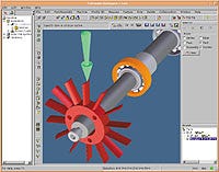
 SolidDesigner Version 7.0 allows the designer to set up relative positioning rules for parts and assemblies.
Additional enhancements to Version 7.0 include adaptive meshing features within the Design Advisor module that enable designers to predict model behavior with finite element analysis, and a Sheet Advisor module that includes fold and unfold capabilities for progressive die design.
For more information, contact CoCreate Software Inc. at 970/206-8000.
InCADPlus Offers Seamless Data Translation Process
The data translation process has traditionally been a pitfall for accurate model analysis. This process, which involves saving a model in a neutral format from CAD and then uploading it into finite element analysis (FEA) software, often ends up with data being corrupted in the transition. InCADPlus, the newest offering from Algor Inc. (Pittsburgh), makes the analysis of CAD solid models easier by eschewing the traditional data translation process altogether. Developed as a cooperative effort between Algor and many of the leading CAD solid-modeling companies, InCADPlus can capture a CAD-created assembly or part geometry in coordination with the modelers' application programming interface, eliminating common data translation problems. Solid-modeling programs that contain this capability include Pro/Engineer, Solid Edge, Mechanical Desktop, and SolidWorks. This interoperability is taken one step further with Direct Memory Image Transfer technology, which allows models to be transferred over a network or on a disk if the CAD program and InCADPlus are on separate computers.
Within the CAD programs themselves, a menu selection window has been added to allow for their direct interface with InCADPlus. It also contains a solid-model interface that gives the user access to a suite of FEA capabilities within the CAD programs, including Algor's mechanical event simulation, linear and nonlinear stress, vibration, heat transfer, electrostatics, fluid flow, piping design, and composite materials modules. The meshing capability in particular gives the designer the ability to view the entire model before meshing to determine whether there are any defects, such as surface holes or self-intersecting surfaces.
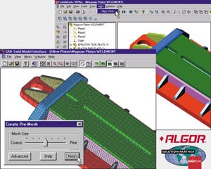
 InCADPlus can be accessed through a menu selection window that has been built into participating CAD programs.
For more information, contact Algor Inc. at 412/967-2700.
IronCAD Version 2.0 Provides 3-D Drag-and-Drop CAD Environment
The latest release from Visionary Design Systems (Santa Clara, CA) provides users with an intuitive drag-and-drop design approach, a design flow architecture that supports the process from concept through postproduction, wire-frame to photorealistic visualization, and interoperability with other CAD systems. While solid-modeling programs have generally applied a real or emulated Windows user interface to traditional mainframe or Unix modeling architectures, IronCAD version 2.0 is billed as the first PC-based solid-modeling software package built with a native Windows solid-modeling architecture. Its TriBall feature allows the user to precisely position any object according to translation, rotation, or any 3-D transformation. Dimension-driven modifications with or without dynamic 3-D constraints can be made to any feature, part, or assembly, including those features in the program's drag-and-drop catalog of stock, bends, lips, seams, hems, and punches.
IronCAD's design flow architecture uses modeling technology that maintains a focus on constraints and parametric relationships while allowing for dynamic 3-D manipulation. This means that models originally built using parametrics can undergo radical design changes without the need to rebuild the model. Casual users can design models without concerning themselves with constraints, parametrics, and feature trees, while power users can take advantage of them if they choose. The user's ability to effectively communicate the design to other members of the design team is further enhanced by IronCAD's visual design features. These features include automatic manipulation of rendering style; fully integrated, real-time texture, decal, and bump maps for representing design details; and effects such as 3-D animation, ray tracing, shadows, fogs, and gels.
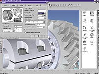
 IronCAD Version 2.0 provides users with an intuitive drag-and-drop design approach.
A variety of tools allow the user to import CAD data from other systems as static reference geometry, or modify them as if they were created natively. For example, 3-D surface data in IGES format can be converted into a solid and can be used to split or trim parts. In addition, polygonal formats such as VRML and STL can be imported, converted to solid with planar and curved surface fitting, and then used natively. And, automatic feature recognition can identify and create features on imported data.
For more information, contact Visionary Design Systems at 800/339-7304.
You May Also Like


