.jpg?width=700&auto=webp&quality=80&disable=upscale "warburton2_EMO_web(1).jpg")


Sign up for the QMED & MD+DI Daily newsletter.
Medical Device Safety System Design: A Systematic Approach
The design of a safety system should be addressed as an integral part of the overall system architecture.
11 Min Read

As technology advances, medical devices that improve disease diagnosis and the treatment of illness or injury are introduced. Many of these lifesaving medical devices perform these functions through the control and measured application of hazardous and potentially lethal energy sources such as x-rays, gamma radiation, lasers, or high-voltage
|
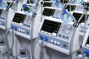
An IEC-compliant emergency-off button mounted on the control console. |
electrical charge. Patients and healthcare providers depend on medical devices to perform safely and predictably in a variety of situations and environments. However, as medical devices become more sophisticated, they increase in complexity and their response to user inputs, environmental inputs, and component failures aren’t as predictable. Therefore, a systematic approach to device safety is essential to the successful and cost- effective development of complex medical devices.
A well-designed safety system must implement risk controls for all of the product’s hazards. For devices that have significant risk of harm, the safety system includes elements that are fully independent of the operational elements of the system. The safety system must also have well-defined interfaces with the operational elements of the system at critical points.
Define Safety Requirements
The process of designing an effective and compliant safety system begins during the product definition phase before product requirements and architecture are defined. In addition to the normal market-driven requirements, at least two other inputs to the medical device’s specifications should be considered. First, potential hazards of the device, identified through the risk assessment process; and second, the domain-specific safety requirements mandated by national or international standards. The medical device development team must consider the intended use of the device as well as the planned product design when analyzing the product for potential hazards. The risk assessment team should include members who are knowledgeable about the typical use of the device including the skill or training of the typical users and the range of normal and atypical, but likely use cases for the device.
The objective of the risk management process, as defined by ISO 14971, is to identify the inherent hazards of the medical device, assess which hazards must be mitigated through safety-related systems or other means, implement appropriate risk controls, and assess the residual risk after the risk controls have been incorporated into the design. This process will help to identify the critical points within the overall system architecture that the safety system must monitor and exert control over. By addressing product risk as an integral part of the product development process, the required safety system can be developed during the product development process and effectively integrated as a part of the system architecture. When developed in this manner, the cost of developing the product is reduced as is the overall development schedule.
Medical Device Design: |
The initial risk analysis will identify many, but not all, requirements for the device’s safety systems. A thorough regulatory standards review is also needed as part of the upfront definition of the product to identify the mandatory safety requirements to which the device must ultimately comply. Typically, system requirements are intentionally structured to avoid explicitly defining the design approach. Regulatory requirements are different. Regulatory requirements are often prescriptive, defining exactly how the standard must be implemented. For example, 21 CFR 1040.10 describes in detail the interlocks and safety components needed for various classes of lasers. These required elements must be included in the product design and as these features are incorporated early into the design their effect on the look and feel of the product to the end user is minimized.
Address Safety in the Architecture
Once the medical device’s risk control requirements and regulatory requirements are identified, they have to be decomposed to identify where and how each requirement will be addressed in the overall system architecture. This effort must occur as part of the initial architecture design to ensure the appropriate allocation of safety functions are made while the design architecture is still fluid. Typically, safety-related requirements are addressed by the following combinations:
System software and firmware.
Dedicated safety electrical hardware such as a complex programmable logic device (CPLD) or field-programmable gate array (FPGA).
A dedicated safety processor and associated software.
Mandated electromechanical safety circuits such as the emergency off (EMO) circuit.
Mechanical guards and interlocks.
Each aspect of the overall system contributes to an integrated safety system. The system software can handle complex rules analysis and decision, and the sequencing of events. It can manage routine error handling and communicate the system state to the user. However, because of the system software’s inherent complexity, it can be difficult to verify and regression test safety-critical functions within the larger code base. Furthermore, unless the safety-related software functions are designed for deterministic behavior, the system’s response to safety event will be nondeterministic and safety-critical operations may be delayed.
Consider an Independent Safety System
A common response to the limitations of system software is to embed critical safety functions into independent hardware such as complex hardware devices, like a CPLD or a FPGA, as illustrated in Figure 1. These devices have the advantage of high reliability, deterministic response and, in the case of simpler devices, the ability to verify the operation with 100% coverage. This means that every possible combination of input conditions can be tested.
|
Figure 1. Product architecture with an independent safety system. |
Another approach used when a device needs a complicated safety system is to design the safety software to execute independently from the device’s main application, often on a separate microcontroller. By keeping the safety software as small as possible, the ability to verify the safety software is improved, and these functions are less likely to be affected by future features added to the medical device. Executing the safety software on a processor separate from the main processor helps to keep the safety software small and further reduces the possibility of the main system software interfering with the execution of the safety software.
Encapsulation of safety-related functions within the system software is the next best thing, allowing rigorous testing of the safety-related functions. The processor and operating system upon which the software is executing must provide a means of isolating the safety-related functions from the operational functions of the device. The architectural features used to provide this isolation must be verified to provide sufficient isolation so that a defect in the software implementing the operational functions cannot affect the operation of the safety-related functions (see Figure 2).
|
Figure 2. Safety software running on the same CPU. |
There are several real-time operating systems (RTOS) that provide this capability when used with a microprocessor or microcontroller that supports a memory management unit or similar hardware support for isolating functions. Without proper isolation, all functions running on the same hardware must be treated at the highest level of criticality of any function running on the hardware. In the case of safety-related functions and operational functions running on the same hardware, without proper isolation all of the functions must be treated as safety related and verified with the same level of rigor.
Another advantage of a design approach that separates safety elements of the system from the operational elements is that it bounds the amount of software and hardware that must be 100% correct. Physical separation is the most definitive. The interfaces between two processors or a processor and an FPGA can be clearly defined. In many cases the safety-related functionality is small enough to allow 100% verification coverage, explicitly testing all possible states of the safety-related hardware and software.
The safety system may also include interlocks, monitoring a number of safety critical sensors and switches. The safety hardware, whether CPLD, FPGA or secondary microprocessor, often contains a watchdog timer for the main microprocessor and will execute a reset or shutdown sequence if the device does not receive a signal from the microprocessor within a specified time window. If a specific set of conditions is not met, the safety system will lock out device operation in a manner independent of the main microprocessor’s control. The main microprocessor can monitor the outputs of the safety system to provide information to the user on the nature of the fault and guidance on how to clear the error, such as “laser access door open.”
Electromechanical Considerations
Some elements of the safety system cannot be implemented in software or firmware and must be implemented using electromechanical safety circuits. The design of these elements is mandated by international standards specific to the type of device and must be designed with agency-certified electromechanical components to ensure compliance. The most obvious example of this is the EMO circuit required on many medical devices. The type of hardware that can be used in an EMO circuit and the level of redundancy required is prescribed by numerous standards, depending on the hazard level and energy source. Even the location and appearance of the EMO button is mandated. If these mandated requirements are identified in the definition phase, it will be much easier to incorporate the electromechanical components into the architecture and detailed design.
The advantages of electromechanical safety circuits are that they are simple and robust, and their design has been proven in countless consumer and industrial applications. Where design teams often go wrong is in trying to “improve” on these safety circuits by incorporating nonagency-certified components or nonstandard design approaches. This can lead to delays in third-party evaluation or a late-stage redesign. If the safety circuit is designed according to the applicable standards however, the third-party evaluation process should be straightforward.
Good Safety System Design
When the team is making decisions about the architecture of the safety-related systems, several characteristics should be considered in its design. The safety system should be the following:
As simple as possible to achieve the desired safety functions.
Functionally independent of the main control system.
Have well-defined interfaces with the main control system.
Fully verifiable as a module or modules.
Obvious in both design and operation.
Any system of sufficient complexity will have design flaws and unintended behaviors – medical devices are no exception. Functional independence of the core functional system and the safety system can be thought of as a firewall to limit the effect of these defects. The following are some examples of common design flaws.
Sneak Circuits. A sneak circuit is a designed-in signal or current path that causes an unwanted function to occur or inhibits a wanted function.1 An example is an unintended current path in a circuit that pulls a microprocessor input high under the right conditions, throwing the software into an undefined state.
Common Cause Failures. This includes common mode, cascading failures, and single-point failures. An example of a single-point failure is the use of redundant thermocouples connected to a common A/D convertor to control the temperature of a heater. Failure of the A/D convertor will result in incorrect readings from both thermocouples and a potentially hazardous situation.
These types of design flaws can be avoided if they are considered in the hazard analysis, requirements definition, and system architecture phases of the development cycle. The safety system should be as independent as possible from the system that it is monitoring. Software operating limits may be supplemented by fail-safe safety limits that act on the energy source through a mechanism other than the one used by the main control software. Critical safety devices such as laser beam stops may need to have separate independent means of actuation.
A common example of a functionally independent safety system for such a heater would consist of microprocessor-based temperature control based on the thermocouple input, in conjunction with a separate electromechanical over-temperature switch that interrupts the heater power circuit, if there is an over-temperature condition. Because this safety system is functionally independent and uses a different design approach than the main heater control loop, the potential for an unintended interaction is reduced.
Review the System Architecture
One method to evaluate how well the team is implementing the safety architecture is to review the product architecture. Some questions to ask include:
Are all of the safety requirements addressed by the architecture?
Does the architecture describe how the safety-related functions are isolated and protected from other aspects of the system?
Can the safety-related functions of an electronic design be contained on one or two pages of the system schematic, or are aspects of the safety system spread throughout the entire document?
Are the software based safety functions well encapsulated, with clear inputs and outputs, or are aspects of the safety functions spread throughout the code in a way that defies easy comprehension of the way the safety system functions?
Conclusion
The safety system of the device will be reviewed by both internal and external experts and laymen. A system that is well architected from the beginning of the development process and obvious in its function will be easier to document. Clear documentation is easier to review and flaws in the design will be more evident.
The resulting design will provide clearly defined mitigations for the device’s hazards. Most importantly, the safety features of the medical device will be comprehensive and robust enough to provide users with protection against many hazards during its use in real-life situations.
References
JP Rankin, “Sneak Circuit Analysis,” Nuclear Safety 14, no. 5 (1973).
David Warburton is the director of Systems Engineering at Foliage (Burlington, MA). Dan Goldman is a lead medical device system architect at the firm.
About the Author(s)
You May Also Like