
Sign up for the QMED & MD+DI Daily newsletter.
Above are silicone extrusion, silicone-molded, micromolded, and two-material molded parts.
Jeff Randall
September 1, 2010
11 Min Read
.svg?width=850&auto=webp&quality=95&format=jpg&disable=upscale "Juggling Act: How to Design with Multiple Materials")
Just a few decades ago, choosing the material for a new medical product was a relatively simple process limited to a few commodity materials. Today, that’s no longer the case. Product designers can choose from a wide array of materials with distinct properties, from bioinert and ecofriendly parts to drug-eluting and bone-emulating components.
Furthermore, manufacturers can more easily combine two or more materials into a single piece. This method helps to reduce manufacturing costs and produce the intricate components that the medical industry increasingly demands. Because material properties can be precisely and strategically placed where they are needed, designers have options that didn’t exist just a few years ago.
Device makers face a delicate balancing act of creating innovative products that use new materials while taking into account the feasibility of manufacturing such items. Too often designers err on the side of caution, using design guidelines based on a familiar manufacturing process when a more-effective process or combination of processes would yield superior results. An optimal design requires collaboration with the manufacturing partner early in the design process.
First, it may be helpful to review some of the primary methods for combining two or more materials into a single part. The two main categories are assembly (two components are created separately and later joined together) and multicomponent molding (combining multiple materials during a molding process).
Mechanical Assembly
Mechanical assembly consists of snap-fits, fasteners, taper locks, tethers, and other mechanical means of maintaining the assembled relationship of the components. This method may be appropriate if relative motion between the various components is required, to prove a concept during the development of a product, or if the quantity needed does not justify the capital expense of more advanced methods.
Designing for mechanical assembly requires the inclusion of features–the aforementioned snap-fits and taper locks, for example–that otherwise wouldn’t be required. These added elements take up space and often increase tooling costs to incorporate side-actions, lifters, or stepped parting lines. After the components are manufactured, labor or automation is required to complete the assembly.
Tolerances are a key consideration, because manufacturers must ensure that process variation and all cavity combinations will produce a consistent result. Because loose-fitting assemblies are generally not preferred, features are designed in tension (i.e., residual stress). Environmental factors such as service temperature, load, exposure to chemicals, and service time may result in dimensional and performance changes due to creep (relieving the internal stress) or environmental stress cracking (ESC). While creep and ESC should be considered in any design, the spring-like features commonly used in mechanical assemblies are especially susceptible to these phenomena.
Chemical Assembly
Chemical assembly employs either adhesives to bond two components together or solvents to plasticize the mating surfaces. This method may be appropriate if relative motion between the components is not desired or if the materials are not compatible with more advanced processes. It’s also sometimes used during product development to test a concept. Again, labor or automation is required to complete the assembly. One notable advantage of chemical assembly is a simpler joint design compared with mechanical assembly.
Good manufacturing processes for chemically joining components include banning mold release agents, employing cleanrooms (surface cleanliness is vital to achieving a good bond), and incorporating plasma treatment to increase the quality of the surfaces and promote adhesion. Manufacturers must be particularly attentive to the curing method of the adhesive, outgassing of volatile components, environmental stress cracking that may occur, and the biocompatibility of the added material.
Thermal Assembly
Thermal assembly techniques include welding– whether using ultrasonic, vibration, hot plate, or laser methods–and heat staking. All of these processes create a permanent assembly by melting one or both of the components at the joint. Because remelting of one or both of the components is the means of attachment, these methods require the use of at least one thermoplastic material.
Like any assembly technique, thermal adhesion has its challenges. The process of joining two components through melting is especially difficult to control with semicrystalline materials. When their melting point is reached, these substances flow freely. On the other hand, amorphous materials soften over a broader temperature range, which renders them more easily controlled and formable.
Hermetic seals are achievable depending on the material selection and the design’s allowance for spill out (excess melted material around the joint) and tolerances. A healthy safety factor, a robust process, and a high rate of testing are recommended to ensure an acceptable bond due to the relatively uncontrolled movement of the materials during this joining process. Surface contamination, including particulate, mold release agents, and surface oxidation can inhibit the formation of a good bond.
Induction sealing is commonly used to seal bottles or other containers. The liner on a ketchup bottle is a prime example. This process requires trapping a coated material—generally an aluminum foil coated with a thermoplastic material—between the two surfaces to be joined. The assembly is exposed to a magnetic field, which induces current in the foil, generates heat, melts the thermoplastic coating, and sticks the components together.
|
These micromolded parts can be used in medical applications. |
Multishot Molding
There are two main ways of molding multiple pieces together–multishot molding and overmolding. Multishot molding involves injecting more than one material into a mold during a single molding cycle. Although this practice has been around in the thermoplastic industry, more recent developments include the ability to combine thermoplastic injection molding with liquid silicone injection molding. The process is a bit more challenging than conventional thermoplastic multishot molding, but its ability to include liquid silicone allows the designer to take advantage of the material’s unique properties.
The most common multishot process uses a rotary platen in a two-shot molding press. One side of the mold (generally the operator side) is the first-shot side and the other side (nonoperator) is the second-shot side. To begin the cycle, the cavities on the first shot side are filled with the first material. When the material has sufficiently cooled, the mold opens with the parts staying on the cores; the movable platen rotates 180°, and the mold closes, introducing the first shot parts to the second shot cavities. The second material is injected into the second shot cavities, thus encapsulating, or overmolding, the first shot parts. When the parts have cooled, the mold opens and the platen rotates 180°. Then the finished parts are ejected, and the mold closes for the next cycle. A new first shot is injected simultaneously with the second shot to initiate the next cycle.
Other adaptations of this process produce the same overall effect using different means. For instance, manufacturers sometimes use a rotary mold (the mold rotates instead of the platen) or a rotary stripper plate, whereby parts are lifted off the cores on a stripper plate and the stripper plate rotates and introduces the parts to new cores and cavities. A core-pull process involves molding a first shot and then moving a core (whilte the mold is closed) to create a cavity for the second shot material to fill. The major benefit of this process is the ability to fit many more cavities in a given press size than would be possible with a rotary platen or rotary mold.
All of these variations have advantages and disadvantages for certain applications. In general, multishot molding results in a high-quality bond between compatible materials, no work-in-process components to inventory and handle, and simplified production scheduling. Because thermoplastic parts continue to cool and shrink long after being ejected from the mold, a multishot process may result in less molded-in stress because, other than the cooling cycle of the first shot, the materials shrink together. If the materials have similar shrink rates, this can be a significant plus. If they have dramatically different shrink rates, warping is the likely result.
Another potential advantage of multishot molding is that the parts never leave the core from the first shot through the second shot process. This saves the time and expense of fitting a first shot component into an overmolding tool. The benefit is greatest when the components have complex core geometry or undercuts opposite the overmolded area of the part.
Multishot molding has a number of drawbacks, too. If the materials are not compatible– that is, they don’t form a suitable bond–features must be included to create mechanical interlocking. This can be tricky if the standard “common core” approach is used. Options to improve bond strength, such as surface preparation via plasma treatment or application of a primer, are limited to whatever can be done in the press between molding cycles, thus extending the overall cycle time. Additionally, unless core-pull technology is used, a much larger press is required than would be necessary for either the first or second shot.
Overmolding
Once viewed as a less expensive substitute for multishot molding, overmolding offers some unique advantages to the designer. In overmolding, a material is molded over or onto another component. The insert or substrate is loaded into a mold (manually, robotically, or on a carrier reel) and the mold closes, shutting off on the insert. The insert can be virtually any material as long as the mold can seal against it without causing damage to the insert or the mold.
Because of the flexibility in materials and processes that can be combined with overmolding, this process can be considered a hybrid method. One can use virtually any material (thermoplastic, liquid silicone rubber (LSR), gum silicone, Teflon, stainless steel, titanium, etc.) from virtually any process (injection, compression, or transfer molding as well as extrusion, thermoforming, machining, etc.) as an insert for overmolding.
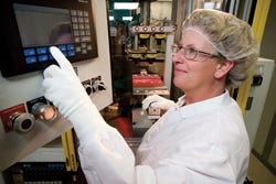
|
A technician leverages robotics and automation to mold inserts. |
Because the insert is loaded into a new cavity and core, the overmolded part detail can wrap around the insert. The part design options are greater than even the stripper plate method of multishot molding because there is no need to maintain features to keep the part on the stripper plate during rotation. With a little ingenuity, the entire surface of the insert can be overmolded in one operation.
To improve the joining of dissimilar materials, mechanical interlocking features are often used. Overmolding allows the designer the freedom to include these features with fewer restrictions.
Plasma treatment is often used to clean and excite the surface of an insert to be overmolded. Plasma treatment may be used with or without the application of a primer or adhesive to improve the bond. Applications using materials that resist bonding, such as silicones, often require plasma treatment or priming to achieve an acceptable bond. The overmolding process allows the application of these treatments in lot quantities without interrupting the molding process, which would be required using multishot molding. Since most primers require time for volatile components to evaporate and become activated before overmolding, the overmolding process is superior to multishot molding when primers are used.
Collaboration Yields ?Possibilities
In some cases, device designers abandon design options for a new component based on limited or slightly outdated information about the various production techniques available to them. It’s important for designers to realize that manufacturing capabilities are constantly evolving to satisfy customer needs, just as their finished products adapt to the changing needs in the marketplace.
Creativity can be stifled if the designer is too concerned with manufacturability. During the initial phase of product design, the manufacturing method shouldn’t even be a consideration. Indeed, many of the multimaterial products that have been developed in recent years required creative, highly customized processes. In one case, I helped to create a single device that incorporated 10 components and 12 different manufacturing processes. It involved LSR molding (including a micromolded component), stainless-steel wire that was bonded, and jacketed by a multilumen silicone extrusion, Teflon tubing, overmolded stainless-steel tubes with an engineering-grade thermoplastic material, two purchased components, mechanical assembly, plasma treatment, adhesive bonding, testing, labeling, and pouching.
Such creations simply aren’t possible without a true partnership between the manufacturer and designer. Early on, the focus should be on the shape and physical properties required of the product. Only after design concepts are identified should the project team begin brainstorming manufacturing options. This is the ideal time to include a manufacturing partner in the discussion. Working with a manufacturing partner that is proficient in a variety of processing techniques will provide unbiased input to help the designer optimize device performance while controlling costs.
This method unleashes the manufacturer’s expertise and creativity, sometimes resulting in solutions that wouldn’t have come about otherwise. It also gives the contractor insight into quality issues that may affect the way production tooling is designed—for example, gate placement and parting lines. Armed with confirmation of a viable manufacturing approach, the device maker can finalize the design.
Conclusion
Designers who limit collaboration in order to keep their supplier options open sometimes commit to a manufacturing process that may not be ideal for the product. Locking in the manufacturing method before consulting with your manufacturing partner may, in fact, lead to an inferior design with higher tooling and part costs. Communicating the desired functionality of a part early on leads to a more robust design and aids manufacturers in their preproduction planning. This method gives manufacturers a jump-start on the road to product launch.
Jeff Randall, PE is vice president of engineering at MRPC (Butler, WI).
About the Author(s)
You May Also Like


