Harnessing Laser Ablation for Polymer-Based Devices
MACHINING
January 1, 2008
|
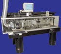
Laser lathe systems prevent crimping damage to catheters by using pneumatic-controlled collets. |
Advanced machining technology has become a viable way to keep medical device manufacturing successful in the United States. One such technology is laser ablation, which has many applications for machining polymers. Laser ablation is a process in which a laser vaporizes (ablates) the polymer material, breaking molecular bonds and transforming the material from a solid phase to a gas phase. The ejected ablated particles rise upward in a plasma gas and are captured in a remote debris nozzle, making certain that the removed material is separated from the machined area. This article reviews laser ablation processes to help manufacturers understand the technology's capabilities.
A Scalable Process
Manufacturing thrives in the United States. Although moving manufacturing operations offshore can be economically attractive, many minimally invasive devices are still manufactured in the United States.
It is commonplace to visit a medical device firm and see rows and rows of assembly benches in a cleanroom, with seated operators hunched over magnifier viewing scopes performing an assembly step such as tipping a catheter or affixing a device to a guidewire. As a result, a common observation is that there is less automation in the device industry than one would expect.
Once a device has gone through its product development stage and the design has been frozen with the initial manufacturing processes validated, many firms are reluctant to go back and change the process. The effort required to do so can be significant—and with so many other regulatory and clinical obstacles to overcome, the efforts of the development and manufacturing engineering teams are often focused elsewhere.
|
Laser ablation can account for raw material variability, such as the thickness of a catheter wall. |
This is especially true of smaller medical device companies that do not have the resources to go back and revalidate a process. However, such changes are not unheard of at large device companies—large firms often perform a return-of-investment analysis. Vascular companies that have been hurt by slumping stent sales, for example, might focus on whatever activity brings the company the most short-term revenue.
Once everything is approved, operations spring into action to quickly build up inventory in the hope that revenue can recoup the significant development and regulatory costs. However, there is a growing trend in medical device design to involve critical suppliers at earlier stages. The suppliers' processes are then incorporated into the validation protocol, and this step improves the scalability, quality, and consistency of the process.
| Laser-Friendly Polymer Materials ABS* *Bioabsorbable polymers |
One of those scalable processes is the laser ablation of polymer-based or plastic devices. The technology facilitates automation of the manufacturing process and can be used on products such as polymer-coated wires, multilumen catheters, polymer wire-mesh encapsulations, angioplasty balloons, and diagnostic sensors. For all these devices, some type of manufacturing process—cutting, stripping, drilling, skiving, or tipping, for example—must be performed on a plastic material. These materials include polyurethane and nylon as well as several bioabsorbable polymers (see the sidebar, “Laser-Friendly Polymer Materials”).
Laser Skiving and Hole Drilling
Many device firms manufacture multilumen catheters for drug-delivery applications. Small round or oval holes must be drilled or skived in the outer lumen. Hot needles, drill bits, or scalpels can drill holes that are 0.001–0.04 in. in diameter during prototyping. But these techniques lack repeatability and consistency, often leaving flaps or jagged edges. Laser ablation technology can drill or skive holes with tolerances of ±0.0005 in. with a Cpk (a process capability index) greater than 1.3.
Most medical device companies expect the Cpk to be greater than 1.3, because at this level, there is generally enough confidence that the process can be inspected through a sampling plan rather than performing 100% inspection. For most laser ablation processes, the Cpk runs between 1.5 and 2.0. The process produces excellent skive quality with sharp, clean edges.
A catheter, for example, can be fed into a laser lathe system and held in place by pneumatic-controlled collets to prevent crimping damage. The catheter is rotated by a single or pair of direct-drive rotary stages (not belt-driven stages, which can often slip and cause positioning errors). The direct-drive mechanism is mounted on an x-y stage with high-speed linear encoders with accuracy of ±1 µm, providing three degrees of freedom: x, y, and θ.
To account for extrusion variability such as wall thickness or lumen twisting, techniques such as run-out compensation and autofocus are used as in situ processes. Multiple camera systems with high-speed capture software allow the laser system to simultaneously adjust the x, y, and θ planes to maintain hole size and center the holes along the axial direction of the catheter or lumen wall.
A critical aspect of laser ablation technology is its ability to account for raw material variability, such as extrusion dimensions, to maintain critical features. For example, laser drilling is affected by the thickness of the catheter wall. As the laser drills, there is a taper angle of approximately 3º–5º with respect to the vertical alignment, which creates a hole diameter that is smaller at the inner diameter (ID) than the outer diameter. The taper angle governs the delta between holes. If the wall is thicker than expected, the hole diameter at the exit (or ID) is smaller. If the wall is thinner than expected, the hole diameter at the exit is larger.
A stainless-steel, tungsten or Teflon-coated mandrel is inserted into the central lumen to provide mechanical stability. For long peripheral catheters, one end is supported by v-grooves to ensure straightness. Smaller mandrels are inserted into the appropriate satellite lumen that requires holes to be drilled. The laser beam enters the catheter from the top (perpendicular to the catheter axis) to drill the hole, while the mandrel prevents the beam from hitting the back side of the catheter wall. The laser beam acts like a virtual tool bit and can be fashioned into any shape, such as a circle, oval, or rectangle.
Laser Stripping
|
A laser stripping system uses pulses to peel layers like onions. |
Sometimes device manufacturers need to remove an outer layer of polymer material to expose an underlying metal layer such as a wire or mesh. Depending on the application, they may want to observe careful, controlled depth so that the underlying layer is not disturbed, or they may want to expose a metal boundary to provide an electrical contact. Prototyping methods for these processes include bead blasting, hot irons, or mechanical wire stripper tools. But these techniques are inconsistent and often depend on the operator's skill. They may also produce poor yields.
Laser ablation is a selective process that can machine one material without affecting the underlying material. The technology offers a repeatable, consistent process because a polymer's ablation threshold, or the amount of laser energy density required for ablation, is an order of magnitude less than the threshold of metals. The laser can etch the polymer material and once it reaches the metal, it can hit the metal boundary for an extended period of time without any visible effect (because the energy density is too low). Each laser pulse removes approximately 0.1 µm at a time so that the outer layer can peel like an onion, layer by layer.
Laser Ablation of Three-Dimensional Devices
|
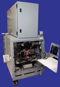
Machine vision on a nine-axis system maps 3-D profiles to account for geometric variation. |
Some manufacturers need to perform complex machining on a 3-D device with conical (nonplanar) surfaces and with geometry (conical angle, outer dimensions) that varies from part to part. One prototyping method entails an operator holding the device with tweezers under a magnifying lens and using a series of mechanical tools to shape the device. Laser ablation offers a one-stop method to machine the polymer-based 3-D device.
Similar to laser lathe technology, the device is mounted on a direct-drive rotary with x-y motion. To accomplish true 3-D machining, three additional axes—z, yaw, and tilt—are added to achieve six axes of motion. A separate mask stage with x, y, and θ is added to help machine complex patterns without stitching errors. The result is nine degrees of motion, all synchronized like a full-piece orchestra, playing to the rhythm of a rapid-firing laser. Laser machining is achieved by scanning the mask stage across a stationary beam while simultaneously rotating the device about the six axes of motion.
|
A nine-axis system can provide maximum yield for components such as this laser- machined screw. |
The nine-axis system is equipped with machine vision that automatically maps the 3-D profile prior to laser machining. This accounts for geometric variation. The 3-D geometry is captured by the computer so that the system automatically compensates for dimensional variation (such as cone angle) to guarantee maximum yield, independent of raw material variation.
It's important to note that in some cases—vision system requirements, for example—significant financial investment is required. Some ablation firms are investing millions to automate their manufacturing processes (nine axes, automapping, autoloading, etc.). Unless U.S. laser manufacturers are willing to make some key investments in this type of infrastructure, device manufacturing may continue to move offshore.
|
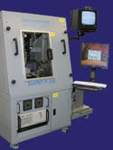
An in-line camera viewing system allows a variety of parts to be excised. |
Laser Excision of Polymer Films
Certain devices require a manufacturer to excise polymer film into individual devices or to remove the gates from a tree mold. Mechanical methods for this process include die stamping or using razor blades and curved scalpels to excise the devices. These methods are not easily scalable to automation and often leave unacceptable cut quality or burrs.
|
Table I. (click to enlarge) Various types of laser sources with their wavelengths and applications for machining polymers. |
Laser ablation uses short-pulse, short-wavelength lasers (see Table I), such as diode-pumped solid-state lasers at 355 nm and 266 nm, to direct-write a small focused spot (typically 10–25 µm in diameter) around the cut profile at repetition rates up to 100 kHz. The ultraviolet wavelength is absorbed into the polymer material, which results in a clean ablation—literally vaporizing the material into a gas phase—without melting or creating a heat-affected zone. By using a galvanometer-driven optical scanner that manipulates the beam direction through a pair of spinning mirrors, manufacturers can program the laser system to cut out any small part using a computer-assisted drawing conversion software package. Machine vision with an in-line camera viewing system allows an array of parts to be excised, with the option of both global and individual part alignment.
Laser Cutting of Bioabsorbable Polymers
Manufacturers may need to machine fine features into an expanded PTFE weave fabric or bioabsorbable material. They can use die-cutting, razor blades, micromolding, or interweaving polymer strings to cut windows into weave fabrics such as stent covers, or to create scaffold structures in polymer stents. Laser ablation can offer a rapid prototyping, tool-free method to machine tolerances approaching 5 µm. The low-melt-transition characteristics of these materials require laser sources of extreme short-pulse duration (pico to femtosecond) or short wavelengths (157 nm) to machine precise features without melting or discoloration.
|
Short-pulse lasers can machine precise features without melting or discoloration. |
Future Considerations
To keep device manufacturing competitive in the global marketplace, advanced laser micromachining technology is a good start, but it is not sufficient. Consider these three key steps in device machining:
Loading and unloading of the device.
Laser machining of the device.
Inspection of the device's critical dimensions (to ensure Cpk greater than 1.3).
Without the device industry focusing on all three aspects, the trend to offshore manufacturing will accelerate to drive down costs. Even if capital equipment is installed overseas, automated processes are still desirable as they help create more-efficient manufacturing operations.
For example, automated catheter-loading systems can reduce labor costs by utilizing a trough that can hold a few hundred catheters at once. An indexer pulls a catheter into the correct position to allow a laser beam to machine the part by any number of methods described in this article. After machining, the indexer withdraws the device and routes the finished device into go/no-go bins.
Programmable, stand-alone inspection systems exist that automatically measure the critical dimensions of devices. However, this approach requires part handling to load the devices on the metrology equipment, and that slows down the overall throughput. It would be more efficient to perform in situ metrology while the part is still in the laser system but without increasing the overall machining time. This issue highlights the need for parallel processing to prevent any additional overhead that would impede the productivity of the laser machining process.
Laser ablation technology offers device OEMs a road map to perform various simple and complex machining operations on polymers. It can offer scalability for volume manufacturing while maintaining micron-level dimensional tolerances. Manufacturers may benefit from using laser companies, laser system integrators, and contract manufacturing service providers to reduce costs through automation and novel processing techniques.
Glenn Ogura is vice president of marketing at Resonetics LLC (Nashua, NH). Ogura can be contacted via e-mail at [email protected].
Copyright ©2008 Medical Device & Diagnostic Industry
About the Author(s)
You May Also Like


.png?width=300&auto=webp&quality=80&disable=upscale)
