Producing Bubble/Taper Tubing for Medical Applications
Medical Device & Diagnostic Industry MagazineMDDI Article IndexOriginally Published January 2000COVER STORYThe extrusion of tubing that features an integral connector requires a thorough knowledge of the process and precise control of forming parameters.
January 1, 2000
Medical Device & Diagnostic Industry Magazine
MDDI Article Index
Originally Published January 2000
The extrusion of tubing that features an integral connector requires a thorough knowledge of the process and precise control of forming parameters.
Over the years, medical device manufacturers have benefitted from the availability of an increasing number of specialized tubing designs. Among the tubing products that have figured prominently in recent device development are microbore and multilumen tubing, heat-shrink tubing, multilayer and radiopaque tubing, and tubing with various reinforcements. Another tubing product-known as bubble tubing-was created to solve the particular processing and assembly problems that can occur when tubing is joined to a connector.
Medical tubing produced with an integral connector is referred to as bubble or taper tubing. The simplest design is a single-lumen tube with a short section of large diameter that tapers to a longer section with small diameter. The end of the large-diameter section acts as a connector to another device such as a valve or fluid bag, and the small-diameter length is the functional part of the tube (Figure 1).
 Figure 1. Bubble tube with connector.
More-complex designs can also be produced. Multilumen tubing provides multiple paths for fluid flow, guide wires, or wires for connections to electronic equipment from transducers or other devices inserted in the body. The large-diameter opening at the bubble end again acts as a connector and facilitates wire insertion. Bubble tubing can also be produced as a coextrusion. Examples of coextrusion designs are tubing with a stripe or multiple stripes or layered tubing fabricated from different types of plastic. Another variation is tubing designed with more than two diameters.
As a connector, bubble tubing replaces molded parts solvent bonded to a tube or assemblies consisting of a short piece of large-diameter tube solvent bonded to a long piece of small-diameter tube. Bubble tubing offers several advantages with assembled tubes. First, it eliminates the labor cost associated with bonding two pieces of tubing together. Second, bubble tubing requires no solvents, which can be difficult to work with and irritating to assembly personnel. Third, the solvent bond has a high risk of being defective; bubble tubing eliminates this risk and the cost of rejected parts. Finally, the bubble tubing configuration provides a smooth transition between the differently sized tubes, enhancing cleanliness and fluid flow.
EXTRUSION-LINE DESIGN
The basic components of an extrusion line for bubble tubing include an extruder with tubing die, a cooling and sizing tank, and a combination puller/cutter (Figure 2). In addition, air regulators are provided to inject air into the tube when needed for size control.
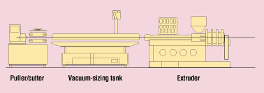 Figure 2. Basic tubing extrusion line.
Plastic raw material is melted and delivered to an annular die mounted on the end of the extruder. The extruder melts the plastic and develops the necessary pressure to force the molten resin through the die. The die opening is generally larger than the finished tube size; the ratio of the diameter of the die opening to the finished tube diameter is referred to as the drawdown ratio.
A puller, using either belts or rolls, is positioned downstream of the cooling/sizing tank and moves the tubing through the tank. The speed of the puller is set at a velocity somewhat higher than the linear velocity of the extrudate as it exits the die. This stretches or draws the tubing down to a smaller size. The drawdown and other process techniques—such as pressure applied to the interior of the tube and/or vacuum applied to the exterior—establish the finished tube size.
FORMING CONSIDERATIONS
Bubble tubing is produced by increasing and decreasing the puller speed to change the drawdown and thus create a different tube diameter at each speed. The acceleration, deceleration, and time duration of the speed changes are adjusted to set the required transition length between the diameters. Air pressure can also be applied inside the tube through the die to assist in setting the tube size and wall thickness. If necessary, the air pressure can be changed at the same time speed changes are made in order to affect wall thickness dimensions.
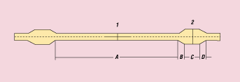 Figure 3. Bubble tube showing sections of differing diameters.
Figure 3 depicts a simple two-diameter bubble tube. To form such a product, the puller first runs at a speed that results in a drawdown to produce the smaller tube diameter of the functional part of the tube, shown as length A. The puller then decelerates to the lower speed for the transition length B, to the lower speed which results in the desired connector diameter for length C. The last segment of the complete cycle, which is the transition length D, is again produced by accelerating the puller to the speed corresponding to the small-diameter drawdown. The puller is programmed to repeat this cycle to produce additional bubble tubing.
As indicated previously, air can also be applied internally to the tube to aid in controlling tube size or wall thickness. If the puller speeds are established for the small-diameter section A and the bubble section C without any pressure changes, the wall thickness and diameter will change at the same ratio. That is, the diameter and the wall thickness will increase in the same percentage for the bubble length.
Some tubing designs require the ratios of the wall-thickness and diameter changes to vary. An example of this would be a design in which the tube wall remains the same thickness for both the small-diameter length and the bubble length. To accomplish this, air pressure inside the tube is changed at the same time that puller-speed changes are taking place, altering the drawdown ratio that would occur if only puller speed were changed. In the example above where the wall thickness is constant, air pressure inside the tube would be increased at the same time the puller speed is decreased to make the bubble. The reverse takes place during the transition from the large- to the small-diameter section of the tube. The puller also delivers the tube to an on-demand cutter, which is activated to cut the tube at points 1 and 2 to create a tube with an integral connector.
COOLING AND SIZING
The cooling and sizing tank used in bubble-tubing production can be either an open water bath or a precision vacuum sizing tank. When a water bath is used, the tubing enters the immersion cooling bath through a round opening in the entry tank plate from the die, as shown in Figure 4. The opening in the tank plate must be slightly larger than the bump section of the tube in order to allow the tube to pass into the tank.
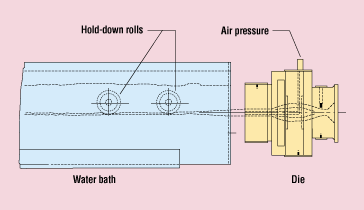 Figure 4. Free extrusion with water bath.
Sizing of the tube is accomplished through drawdown, which can be adjusted with the puller speed and through air pressure supplied by a very closely regulated adjustable pressure source introduced inside the tube through the die. As related earlier, the puller speed and air pressure are adjusted to help form the diameter and wall thickness of the tube design for both the bubble and small-diameter lengths of the tube. These parameters are then automatically cycled between the varying settings to produce the tubing. The major benefit of water-bath cooling is that it involves lower equipment cost compared to a vacuum sizing tank.
The disadvantages of water-bath cooling are associated with tubing quality. In the water-bath process, the weight of the tubing combined with the weight of the water can cause the tubing to become oval. The water bath does not provide a means of ensuring that the tube remains round. In addition, water flowing from the opening in the entry tank plate can cause distortion of the tube. As the bubble passes through the opening, very little water flows past the tube and out of the entrance because the entry opening is sized to the bubble diameter. But at the transition from large to small diameter, a good deal of turbulence can cascade over the tube. The resulting variable cooling effect distorts the tube.
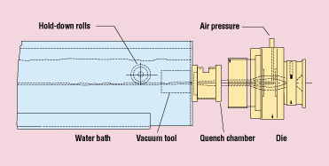 Figure 5. Noncontact vacuum sizing.
A precision vacuum sizer using noncontact sizing tooling can also be used for bubble tubing. In this method of processing, a water quench chamber is mounted at the entrance of the vacuum cooling chamber between the vacuum tool and the extrusion die (Figure 5). The quench chamber is at atmospheric pressure and is flooded with water. The vacuum tool through-bore is larger than the finished tube diameter. Negative differential pressure caused by the vacuum in the tank draws water through the vacuum tool to fill the void between the tube and the tool and create a water seal for the vacuum.
As the tube enters the tool, vacuum is applied to the outside surface. The resulting equalized forces around the circumference of the tube hold the tube round while it is cooling. The level of vacuum can be used to regulate the size of the tube as well as to make the tube round. Increasing the vacuum will increase the size of the tube, and vice versa. Since the vacuum level affects the tube size, the vacuum must be very stable, typically within 0.1 in. of water, so that close dimensional tolerances can be maintained. Typical vacuum levels for this method of sizing are from 10 to 40 in. of water.
Drawdown controlled by puller speed and air pressure applied to the inside of the tube are also used to aid in size control of the tubing. The puller speed and air pressure are adjusted to provide the diameter and wall thickness of the tube design for the bubble and small-diameter portions of the tube. The puller speed and air pressure are again cycled between the values associated with the two diameters to produce the bump tubing.
When processing bubble tubing, the through opening of the entrance to the quench chamber and the bore of the vacuum tool are slightly larger than the major diameter of the bubble tube. Special tooling designs are used to create the vacuum near the entrance of the quench chamber. This tooling controls the water at the entrance to prevent it from cascading out of the entrance after the bubble diameter passes through the opening. This avoids the uneven cooling associated with the water bath and guards against distortion of the tubing.
Vacuum sizing has two important advantages over water-bath cooling for bubble-tube production:
The roundness of the tubing is maintained.
Water is prevented from cascading over the transition and the small-diameter portions of the tube.
These characteristics enable processors to maintain smooth transitions between diameters as well as closer dimensional tolerances.
PULLING AND CUTTING SYSTEMS
The combination puller/cutter is the heart of the bubble-tube extrusion system. A variable-speed puller is mounted on a common stand with an on-demand cutter. The puller has a servomotor and controller with precise speed regulation. Servomotors are used because they are designed with low inertia to provide fast response for speed changes. The sensitivity of the puller's speed control ensures tight tolerances for the tube diameters and accurate control of acceleration and deceleration so as to consistently reproduce the transitions between diameters.
The cutter uses a rotating knife to cut the tubing. The knife is mounted on a holder that is activated by a servomotor. Cutter activation must be synchronized to the tubing linear dimensions to accurately cut the tube in the center of both the large- and small-diameter lengths of tube.
A Pentium computer with touchscreen is supplied for control of the puller/cutter and to serve as an operator interface. Functions provided by the microprocessor would typically include:
A length-measuring electronic counter with encoder input. This measures linear tube dimensions for control of bubble length, transition length, small-diameter length, and cut positions.
Motor speed references associated with each of the tube diameters. Rate of change of the speed reference is adjustable for control of motor acceleration and deceleration during the transition between the speed settings.
Output signals for actuating solenoids and servo valves that control regulators supplying air for internal-air size control of the tubing.
The air-supply units for air-pressure size control must provide precise pressure regulation to ensure close tubing dimensional tolerances. Typically, the pressure regulation is ±0.01%. If the transition between tube diameters is short, the air pressure can be switched from one level to another. In this case, solenoids actuated by switched outputs from the puller/cutter microprocessor will first connect a regulator set at one pressure level while the bubble diameter is running and then another regulator with a lower pressure while the small-diameter section is running.
For tube designs with long transitions, a regulator with variable output controlled by a servo valve is used for the air supply. In this case, the puller/cutter microprocessor supplies a variable output signal to control the servo valve and change the air pressure over the length of the transition.
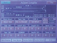 A touchscreen allows operators to monitor puller and cutter speeds and control air pressure; bubble, transition, and small-diameter lengths; and cut positions.
In most cases of bubble-tubing production, the extruded product does not correspond exactly to the dimensions programmed into the puller/cutter. The stiffer the material, the more closely the mechanical change will match the parameters set in the program; with very elastic materials, the operator will have to compensate for material stretching (i.e., rubber-banding) in the programming. The variation between actual and programmed dimensions also increases as the ratio of the large diameter to the small diameter increases.
Let us take as an example a 65-Shore-A FPVC tube having with a small diameter of 0.100 in. and a 0.020-in. wall and a bump diameter of 0.250 in. with a 0.050-in. wall. If the small diameter is running at 100 ft/min, one would anticipate the speed for the large diameter to be 40 ft/min. Running at 40 ft/min may indeed yield a 0.250-in. OD in a straight, nonpulsed mode. However, the rubber-band effect of running at 40 ft/min and then rapidly increasing to 100 ft/min stretches the large diameter and cools it farther down the tank, allowing the part to draw more and resulting in a diameter of less than 0.250 in. Consequently, the puller speed would have to be reduced below 40 ft/min to attain the 0.250-in. dimensions.
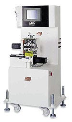 A streamlined bubble tubing extrusion system (RDN Mfg.).
In the same manner, the ramp lengths when changing from large to small diameter and from small to large diameter will be affected by the stretching action. This results in the ramp lengths not being the same as programmed—in fact, many times the programmed length of the two ramps will have to be different in order to achieve equal ramp lengths. This results from the fact that the material reacts differently when puller speed is increased to decrease the diameter as opposed to decreasing the speed to increase the diameter. Stiffer and tougher materials such as urethane will not react as severely, nor will products with smaller ratios (i.e. 1.5/1). Other processing tips for very flexible materials include having the die and sizing tank very close together and using cold water to help set the melt sooner.
The above examples describe cases of plastics not reacting to mechanical changes. In order to establish the specified tubing dimensions, the operator must:
Program the targeted parameters.
Run the tubing in the straight mode to establish line speeds for the two diameters.
Run bubble tubing and adjust parameters to establish requirements for the tubing.
Record required program parameters for future runs.
CONCLUSION
In order to produce consistent, high-quality, close-tolerance bubble tubing, the extrusion system must combine the latest processing techniques with state-of-the-art machinery and controls. The extruder must provide a consistent melt flow, with absolute minimum deviation in melt temperature and pressure. Dies must be designed with minimum inventory and streamlined flow, and the cooling and sizing bath must feature constant water temperature and low turbulence.
Vacuum sizing offers some processing advantages compared with the water bath that can result in higher-quality tubing. The puller should be equipped with fast-response servo drives and close speed regulation. The cutter requires an accurate cut-length system, and air-pressure supply units need precise pressure regulation and the ability either to switch rapidly between pressure set points or to respond to a signal to follow the transition between diameters.
The medical field has been under tremendous pressure to reduce costs. Bubble tubing is a product that provides significant cost savings as well as higher reliability and improved flow characteristics compared with assemblies that have previously been used to make connections with medical tubing. Well-controlled extrusion processing techniques coupled with properly designed equipment provide the means of producing close-tolerance, consistent bubble tubing.
Dave Wille is president and COO of RDN Manufacturing Co., Inc. (Bloomingdale, IL). In his current position sice 1996, he previously served as RDN's vice president of operations for 14 years. The company offers plastic-extrusion equipment and related tooling and machinery for producing a range of tubing and profiles, including systems for bubble tubing, multilumen tubing, and coextrusions.
Photos by Roni Ramos
Return to the MDDI January table of contents | Return to the MDDI home page
Copyright ©2000 Medical Device & Diagnostic Industry
You May Also Like


