Getting the Most Out of High-Speed Motors in Medical Device Applications
In recent years, there has been a surge in demand for brushless dc motors for high-speed applications. A variety of factors have contributed to this trend. For instance, new impeller technology has changed the way modern respirators are designed, making them quieter and more compact. Such performance requires motors that rotate as fast as 50–60 krpm (thousands of revolutions per minute) and are capable of delivering high acceleration and deceleration in synchrony with a patient’s breathing.
August 30, 2011

In recent years, there has been a surge in demand for brushless dc motors for high-speed applications. A variety of factors have contributed to this trend. For instance, new impeller technology has changed the way modern respirators are designed, making them quieter and more compact. Such performance requires motors that rotate as fast as 50–60 krpm (thousands of revolutions per minute) and are capable of delivering high acceleration and deceleration in synchrony with a patient’s breathing. Other examples adding to this demand include surgical and dental hand tools, which—owing to market demands—are becoming increasingly strong and small. One way to accommodate these trends is to use high-speed brushless motors that can deliver the necessary power and performance within the specified footprint.
|
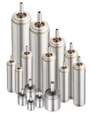
As surgical hand tools become ever smaller, so do the motors that drive them. |
Mechanical power is the product of torque and speed. To increase power, either torque or speed should be increased. Generally, for a given technology, the continuous torque is related to the motor size. Continuous torque is often limited by thermal considerations.
Without considering high-speed constraints, a motor designer will try to optimize the torque that the motor can expend for a given power dissipated by the Joule effect, which represents the relationship between the heat generated by current flowing through a conductor. The figure of merits R/K² (where R represents coil resistance and K is the torque constant) is a good factor to characterize a motor. Ideally, a motor should have a small resistance and a high torque constant. One way to increase the torque constant is to use strong magnets, such as those made of neodymium. To decrease the Joule losses, the wire section should be as large as possible; this will lower the copper resistance. After optimization of R/K², maximum torque for a given motor size is still constrained by its thermal limitation. Consequently, the other parameter that can be used to increase power is speed.
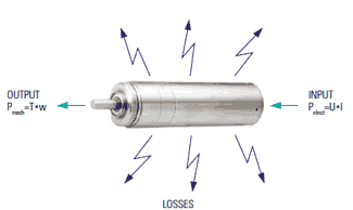
In theory, it seems easy to increase the speed by simply raising the voltage of the power supply. Increasing speed, however, will generate more heat resulting from the following factors:
Iron losses.
Bearing friction losses.
Current ripple–creating losses.
|
Figure 1. The copper losses (Joule losses) vary with the load in proportion to the current squared. They can be expressed as R*t2. Iron losses are the result of magnetic energy dissipated when the motor's magnetic field is applied to the stator core. echanical losses include friction in the motor (bearings and brushes). |
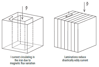
Iron losses owing to eddy current result from the current circulating in the lamination created by the magnetic flux. To decrease iron losses, thinner laminations with high electrical resistance can be used to increase the resistance within the lamination.
Iron losses can also result from hysteresis. The magnetic material used to conduct the magnetic field presents hysteresis. Every time the magnetic flux is reversed, the hysteresis of the material will cause losses. During the design, an engineer will minimize hysteresis losses by using a material such as FeNi.
Iron losses depend on the square of the induction in the iron laminations and on the square of the frequency. For this reason, motors with a high number of pole-pairs will have speed limitations. In many cases, according to the design, a motor with two pole-pairs will have more iron losses than a motor having a single pole pair. It is, however, likely that this motor will have a better R/K2 ratio.
Optimizing a Brushless Dc Motor for High-Speed Applications
|
Figure 2. To decrease iron losses, use thinner laminations with high electrical resistance, which increases the resistance within the lamination. |
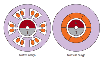
In terms of technology, there are two majors types of brushless dc motors: slotted and slotless. Figures 4, 5, and 6 illustrate these two stator designs.
Slotted Stator Motors. In slotted stator motors, the coils are wound within the slots. Magnetic induction in the lamination is fairly high because the air gap between the laminations (stator) and magnet is small. The volume of the copper is limited by the slot space and by the difficulty to wind within the slot. Having the coil inside the stator slots reduces the thermal resistance of the coil and stator assembly and makes the motor very robust.
Without current, the rotor has preferred magnet positions in front of lamination, generating a cogging torque or detent torque. One way to decrease the detent torque is to skew the lamination. By design, it is possible to build motors with a large ratio of length to diameter.
Slotless Stator Motors. In a slotless motor, the coil is wound in a separate external operation and is of the “self-sustaining” type (see figures 4, 5, and 6). This coil is then inserted directly into the air gap during motor assembly.
|
Figure 3. The above image compares total losses in the motor with speed for a given torque. |
In this design, the magnetic induction in the coil decreases because the air gap increases. Therefore, the motor diameter is often optimized to have the ideal magnetic induction with the optimal copper volume. Usually, induction in such a motor is much smaller by design than in a slotted brushless motor. A relatively large magnet is used to compensate for the loss of induction. Because the inertia of a rotor follows the square of its diameter, the inertia in a slotless motor is usually higher than the slotted motor.
In terms of R/K², a slotless motor has a good figure of merits because induction versus copper volume is optimized. A slotless motor does not have any cogging or detent torque. By design, iron losses at high speed in slotless motors are greatly reduced.
Examples of Applications
|
Figure 4. In terms of technology, there are two majors types of brushless dc motors: slotted and slotless. The drawing above illustrates slotted and slotless stator designs. |
High speed motors for respirators must be able to ramp from a few thousand rpm up to 50 krpm in a few milliseconds in synchrony with a patient’s breathing pattern. The torque needed to spin the impeller is in the range of a few ounce-inches. Most of the torque is used to accelerate and decelerate the impeller.
A new motor family has been recently developed for this specific application, so that Joule losses versus iron losses are optimized to fulfill ever-more stringent needs.
Motors for surgical hand tools must run at high speeds to produce power in a lightweight package, and they must run at low temperature to enhace operability for the surgeon. In addition, they must be able to survive the autoclaving sterilization process.
|
|
Optimizing of the magnetic circuit has made possible the design of a motor 16-mm in diameter that can deliver a few ounce-inches of torque at a speed of up to 80,000 rpm without exceeding 43°C on its housing.
Conclusion
Electric motors are continuously evolving with the constant development of new materials on the market. For each application, it is crucial to understand in detail the specifications in order to offer the optimal design.
Norbert Veignat, PhD, is the vice president, technologies, at Portescap (West Chester, PA).
About the Author(s)
You May Also Like
