

Sign up for the QMED & MD+DI Daily newsletter.
DIAGNOSTICS
16 Min Read
.svg?width=850&auto=webp&quality=95&format=jpg&disable=upscale "Using Automated Cap Inspection to Prevent Medical Errors")
DIAGNOSTICS
|
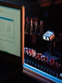
Multilevel and color coding of diagnostic samples enhance sorting. An automated system must be able to pull data from all types of caps. |
Identification errors in clinical laboratory testing for diagnostics have the potential to cause serious patient injury when undetected. Such errors have resulted in Class I recalls. Specimen misidentification is responsible for more documented laboratory errors than any other cause.1 Sample identification errors alone are responsible for 160,900 adverse events in U.S. hospitals annually.2 While the true frequency of identification errors in clinical laboratories is difficult to determine, recent studies point to the preanalytical phase as the weakest point in the process, responsible for an estimated 68–84% of laboratory errors or mistakes.3,4 This phase includes specimen collection, transport, processing, and placement on the analyzer.
Nearly 95% of laboratories participating in a recent study reported using bar codes to automate the identification of tubes and reagents.2 Yet much of the handling of specimens in the preanalytical phase (the initial receiving process and preliminary sorting of multiple sizes of tubes) is still performed by hand. Studies have shown that one out of 300 manually keyed entries results in an error, but only one out of 3 million scanned entries (using a code 39 bar code) results in an error.5 When test results are transcribed manually, there is an error committed approximately every 217 tests.6
Considering these statistics, it is a fair assumption that human handling and data entry increase the chance for error in the preanalytical phase of clinical testing. Device OEMs can help eliminate such errors by expanding the automated data entry capabilities of their equipment.
Device designers already go to great lengths to ensure process errors do not occur. However, diagnostic devices are ultimately only as accurate as the data they receive. Incorporating a cap inspection system provides diagnostic devices and laboratory automation systems with the data needed to automate tasks still performed by hand while also providing additional safeguards against process errors. Cap inspection systems provide the most value for diagnostic devices that function as part of automated laboratory systems. Examples of such devices include automated sample-handling systems, automated aliquotters, hematology automation systems, and automated sample storage and retrieval systems.
Sorting and Diagnostics Challenges
On any given day, a lab handles several types of test tubes for processing. These specimens arrive for analysis from many different sources, ranging from hospitals to doctors' offices. The specimens are collected in a variety of test tubes, which vary in shape, length, and diameter. Some are plastic, others glass. Even their caps vary in size, shape, and functionality. Most importantly, however, these tubes contain different additives designed to optimize the results for specific tests and should not be intermixed.
Tubes have color-coded caps so that users can identify additives contained within. Each color represents a specific additive or none at all. For example, lavender caps indicate that the tube contains ethylenediamine tetraacetic acid (an anticoagulant that is commonly used for hematology). There are 14 cap colors in all, and their meanings are standardized across tube manufacturers. Subsequently, the color of each cap must be accurately identified to achieve a successful outcome of the tests performed on the specimen.
In addition to handling a wide variety of containers, laboratories manage more than 1000 different tests. For example, a large, commercial esoteric reference laboratory reported performing more than 2000 different procedures with an average daily volume of greater than 18,000 accessions. (An esoteric reference laboratory is a facility that provides specialized testing that requires instrumentation or technical staff that are not financially feasible for most hospitals to sustain.) The lab automates 80% of its test volume, which means that the automation system sorts more than 1000 different tests; for many of these tests, an average of only three or four specimens are received and analyzed each week.7 Once initial tests are run, many specimens must be stored for additional testing later. The number of add-on tests for many laboratories has been steadily increasing over the last 5 years.8
The Case for Cap Inspection
By using bar codes to automate data entry and the data-reporting process, device manufacturers can (and already do) prevent identification errors in the clinical process. Yet there is room for improvement. Cap inspection takes the tube identification process a step further by enabling diagnostic devices to further prevent automation mishaps caused by sorting and organizational errors. Cap inspection is performed by a visual recognition system that uses imaging technology similar to that currently used to read bar codes. An imager designed for cap inspection provides information that can be used to identify the tube and cap type before any test is performed. This ability is especially helpful in automating the initial receipt of specimens and in separating chemistry from hematology.
By supplying data about each tube and cap, inspection systems can help accomplish the following:
Automate handling and sorting of tubes of different sizes by identifying color and providing diameter measurements. Increasing device intelligence would also make it easier to automate complex sorting applications.
Prevent pipette crashes by determining if the decapping operation was successful or, if closed-container sampling is being implemented, whether a given cap type can be pierced.
Streamline the fluid aspiration process. Container data make it easier and faster to perform the calculations needed to determine the distance the probe or pipette must travel after the liquid is detected.
Reduce carryover by providing devices with the data needed to ascertain exactly how far to drive the probes. By minimizing excess exposure of the probes to the sera, labs can reduce the amount of washing liquid waste generated in cleaning the probes after each aspiration.
Cap Inspection System Capabilities
|
Improving cap inspection requires a closer look at the automated process. |
To perform cap inspection, the imager measures each tube and cap and matches the dimensions to the test-tube profiles stored in its library. Once the imager finds an exact match, the imager sends the tube and cap type data along with the decoded bar code information to the device. A well-engineered cap inspection imager can collect significant levels of data. For example, the imager can read and decode long linear bar codes as well as high-density 2-D codes such as Data Matrix. It can also provide the device with the tube's position in relation to the automation process. If the tube is present, the device can proceed with the next step. If the tube is absent, it can send an alert message to the host.
By identifying the presence or absence of a cap, the imager helps determine whether the pipettor can proceed. It can also identify test tubes missed by an automated decapper. In addition, by measuring the cap's diameter, the imager helps the device determine whether the cap is pierceable. These data also provide the decapper with valuable feedback.
Additional information about the cap, such as its color and shape, enable the device to identify it from a library of up to a hundred different cap types. The imager should be able to determine the location of the tube's top, and thereby the height of the tube. This information, together with data pertaining to the absence or presence of a cap, as well as the type of cap, allows the system to determine whether the tube is properly seated in the carrier.
Megapixel Imaging Capabilities
Cap identification is already being performed in many laboratories. However, the majority of identification products available for designers of automated diagnostic equipment are much more complex than necessary, sometimes requiring up to 10 sensors to accomplish the same tasks that could be accomplished by one imaging device. To simplify the design process, imaging engineers have worked to develop an alternative, single-component miniature megapixel imager.
|
Figure 1. (click to enlarge) The larger field of view presented by SXGA resolution allows engineers to have greater access to inspection data. |
During the last four years, most array imagers have read at VGA resolution (640 × 480) with 307,200 pixels. This has forced instrument designers to choose between resolution and field of view. The introduction of miniature megapixel imagers with SXGA resolution (1280 × 1024) offers an array of more than 1 million pixels, delivering a much larger field of view without sacrificing resolution (see Figure 1). This large field of view enables mini imagers to read racks of bar coded test tubes simultaneously, or to read combinations of 2-D codes and linear bar codes while also capturing the height of a tube and its cap.
|
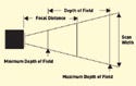
Figure 2. (click to enlarge) An imagery field of view enables 3-D data capture within limited space. |
A large field of view provides design engineers with additional advantages, as it directly affects the amount of space required for capturing the data from the tubes. This space, also referred to as the scan envelope, is the total three-dimensional space required by the imager to capture the data from an object at a specified distance (see Figure 2). Smaller envelopes have the advantage of less cubic space required between the reader and the object. Some mini imagers are capable of capturing an entire tube and its cap within the space of 1 in. between the imager and tube.
Additional considerations include the capabilities and the limitations of the imaging technology itself. It is critical that the information collected by the imager is complete and accurate, because devices and the laboratory automation system will act according to the data provided by the cap inspection system. Many multisensor products typically only provide height information, subsequently requiring all the tubes to be properly seated. An improperly seated tube without a cap may be mistaken for a tube with a cap. In contrast, many mini megapixel imagers use shape information to determine cap absence or presence. Therefore, mini imagers yield the same absence-or-presence answer whether or not the tube is properly seated.
Important Design Considerations
While miniature megapixel imagers can help simplify the design process, specific requirements must be met for an imaging system to function properly within a diagnostic device. Imagers vary significantly in their suitability for embedded applications. Important differentiators include reliability, tolerance for environmental variables, speed, input and output capabilities, power draw, and space requirements. Understanding these variables is essential for finding the best component for a specific diagnostic device.
Image Capture Envelope. Designers prefer compact components, and imagers are no exception. However, more important than the size of the imager is the space required for capturing the desired data. Designers need to calculate the scan or field-of-view envelope before specifying an imager. Especially for embedded applications, smaller envelopes have the advantage of less physical space required between the imager and the object.
Background and Lighting. When designing the physical placement of the imager, the color of the background behind the object to be captured is particularly important. Black backgrounds are much more desirable than white backgrounds for cap inspection applications because they provide the best contrast between the tube and the surrounding device for image processing. Proper illumination of the object is also important. However, most imagers designed for embedded applications already have an array of light-emitting diodes (LEDs). For cap inspection applications, white LEDs are ideal because they provide the color-neutral illumination needed to accurately identify cap color.
Speed. Speed can be misleading when assessing imager specifications. For embedded applications, the decode rate is often more important than the more commonly cited capture rate because it determines how quickly the imager will process the data and send them to the host. It is important to note that miniature megapixel imagers are not designed for high-speed applications, but are better suited for slow or stationary applications. The majority of diagnostic devices use a stop-and-read system for reading bar codes and capturing data, so this should not pose a serious limitation.
Environment. The environment where the imager will be operating should be evaluated. While megapixel imagers are forgiving of bar codes or 2-D codes distorted by condensation buildup on refrigerated containers, the imaging equipment needs the same protection from extreme environments as bar code scanners. Temperature, ambient lighting, electrical noise, and dust or water exposure must all be considered to avoid potential interference with the image capture process. Diagnostic device designers should make sure the housing of the imager meets the necessary industrial rating or build an enclosure to protect the reader from the environment.
Power Consumption. Electrical functions such as power requirements and connectivity cables should be considered when planning the integration of an imager. Most imagers require 5–28 V of electricity. Those designed with minimal power requirements will reduce the drain on the host instrument. The routing of connectivity cables should be carefully designed to minimize the risk of damage.
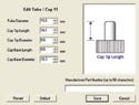
|
(click to enlarge) |
Software and Electrical Interface. Triggers tell the imager when to look for the object. These triggers can be divided into two different categories: discrete and serial. Deciding which type of trigger to use usually comes down to a preference for either programming or wiring. Discrete triggers can be bits from the host system or object detectors that can be wired directly into the imager. Discrete triggers require less programming than serial triggers. Serial triggers are dispatched from an external device, such as the host, which tells the imager when to look for the object. Serial triggers are often used in embedded applications to provide more control over the imager's scan of the bar code.
Additional factors include considering what the cap inspection system should do with the data decoded and how it should interact with the device. For example, an imager may perform basic external electrical functions such as communicate with an auxiliary device to send a confirmation signal for a successful read cycle. The device can be programmed to sound an alarm or discontinue processing if it fails to receive the signal.
Integration. To simplify integration, most miniature imagers output data in standard ASCII text. This facilitates communication with legacy laboratory information systems (LIS) as well as with leading-edge informatics (middleware). Interface software can be used to select and parse the data in a format easily processed by the diagnostic device.
Accommodating Legacy Systems and Future Applications
As with all changes to established processes, integrating a cap inspection system requires planning and careful consideration of the effects the new system may have on the device and its relationship with the laboratory automation system (LAS) and the LIS. Because many diagnostic devices already use bar code identification, integrating a cap inspection system simply expands the data capture capabilities of the device. In most cases, the cap inspection imager can serve as a drop-in replacement for the bar code reader. Since miniature imagers have nearly the same cubic footprint as small laser bar code scanners and share the same power draw, needed modifications to the device should be minimal.
|
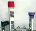
Varying tube sizes may present inspection difficulties if an automated system is not designed to be forgiving. |
Designers looking to integrate a data capture system into a new or existing device will appreciate the greater positioning flexibility miniature imagers offer. The imagers' large field of view and omnidirectional reading capabilities allow them to read bar codes in any orientation and in various directions of travel. High-resolution optics enable them to be forgiving of damaged or low-contrast bar codes as well as to read very small, high-density 2-D codes.
It is well known that many diagnostic devices enjoy a long life once installed in a laboratory. A cap inspection imager's ability to read linear bar codes provides designers with a unique advantage. Integrating a cap inspection imager makes a device 100% compatible with existing linear bar code–based systems yet builds in data capture capabilities for the future that can be enabled easily by a software command.
One of the challenges hospital labs are facing is how to automate the identification and handling of specimens collected in small pediatric tubes. For some hospitals, pediatric tubes make up 30% of their specimen inventory. Currently, there are few automated solutions available for handling and processing such tubes.8 A device with a cap inspection imager designed for this application could have the ability to support existing linear bar code systems and to read tiny 2-D codes on pediatric tubes while also measuring tube height and identifying cap color.
Conclusion
Diagnostic devices are dependent on the accuracy of the data they receive, which is why integrated imagers are very valuable components. The existence of rudimentary forms of cap inspection systems indicates there is already a need for tube and cap identification. New miniature megapixel imagers provide an efficient and effective method for collecting data for embedded device applications.
By providing diagnostic devices with additional data about each tube, cap inspection systems provide several benefits. They make it easier to automate even the most complex sorting applications and eliminate manual data entry while preventing many potential automation mishaps. All of these functions help to build safety into the clinical laboratory process and promote accurate specimen identification.
Andrew Zosel is director of product management at Microscan Systems (Renton, WA). He can be reached at [email protected] or 425/226-5700. Neils Wartenberg is senior field applications engineer at Microscan. He can be reached at [email protected].
References
1. P Bonini et al., “Errors in Laboratory Medicine,” Clinical Chemistry 48 (2002): 691–698.
2. Paul N Valenstein et al., “Identification Errors Involving Clinical Laboratories: A College of American Pathologists Q-Probes Study of Patient and Specimen Identification Errors at 120 Institutions,” Archives of Pathology and Laboratory Medicine 130, no. 8 (2006): 1106–1113.
3. M Plebani and P Carraro, “Mistakes in a Stat Laboratory: Types and Frequency,” Clinical Chemistry 43 (1997): 1348–1351.
4. Beckman Coulter, “The Role of Preanalytical Factors in Chemistry and Immunoassay Testing,” Bulletin 9606 (2006): 1.
5. TJ Mark, “Decoding the Bar Code,” ARMA Records Management Quarterly 28, no. 1 (2004): 22–25.
6. Laura Sciacovelli, Paolo Carraro, and Mario Plebani, “Errors in Laboratory Medicine: Transcription Errors and Interpretative Comments in Report” (paper presented at the Institute for Quality in Laboratory Medicine Conference, Atlanta, April 28, 2005).
7. Charles D Hawker et al., “Automated Transport and Sorting System in a Large Reference Laboratory: Part 1. Evaluation of Needs and Alternatives and Development of a Plan,” American Association for Clinical Chemistry 48 (2002): 1751–1760.
8. Richard Park, “Bridging the Automation Gap,” IVD Technology, 12, no. 7 (2006): 38–45.
Copyright ©2007 Medical Device & Diagnostic Industry
About the Author(s)
You May Also Like


