Sign up for the QMED & MD+DI Daily newsletter.
Critical Feature Confirmation in Complex Medical Assemblies
An expert details the Critical Feature Confirmation (CFC) process, which enables non-experts to offer input on a new medical device design without determining the final critical features. Learn more about the CFC process and how it can speed your time to market.
November 4, 2016
11 Min Read

An expert details the Critical Feature Confirmation (CFC) process, which enables non-experts to offer input on a new medical device design without determining the final critical features. Learn more about the CFC process and how it can speed your time to market.
Edward Jaeck
The design of a new medical device is exciting, but presents unique challenges to new product development teams. Teams must design products with exciting features that provide new functionality while not delaying the product's time to market.
One current practice that can hinder this time to market is the complicated process of critical feature identification which can sometimes entail non-experts weighing in on portions of the new product development process that have no need of their input.
If you struggle with that last line, just ask yourself this question: When was the last time you were asked to weigh in on the supply chain team's next project or the marketing team's new marketing strategy? For the average engineer, the answer is never, and the reason is because you most likely are not an expert in supply chain management or marketing and therefore add little value to the process.
A better solution for today's manufacturers and designers is a process called Critical Feature Confirmation, or CFC. CFC is a process based on designed experiments to determine which features on a device's assembly or component drawing should be designated as critical. The CFC process helps to trim time to market because it allows the non-experts to give input into possible critical features but not the final critical features. Definition of the final critical features is left to the CFC process.
Here, you will learn how the CFC process streamlines the practice of identifying critical features, how to choose skew/limit samples, and how to accelerate your product's time to market with CFC.
Scenario: Design Engineers Face Mounting Pressure to Limit Iterations
It's the start of your next project--the design of a precision-machined medical device.
Your customers were clear on their requirements, and your marketing and engineering teams have successfully flowed down those product requirements into technical requirements. Now it is time for the design engineer to generate toleranced mechanical drawings for individual components and the final assembled device.
There is a lot of pressure on design engineers to get the design right on the first iteration to reduce costs and time involved, and the medical device industry also presents unique challenges. If a design team creates a simple, robust and manufacturable device, then the project team risks taking a boring product with no sizzle to market. If the design team creates something too complex, then the project team risks long delays in the product development timeline and could miss the time to market window for their product launch.
This is where the CFC process can help. By focusing on confirmed critical features, product teams achieve:
Faster designs and review processes, because design departments can focus their design efforts on features confirmed by the CFC process.
Simplified quality control process by focusing test method development on confirmed critical features, and minimizing the amount of data collected during the process characterization, operational qualification and performance qualification phases.
Clean, objective evidence for review by regulatory bodies during submissions.
Streamlined product development process that focuses on the few things that matter, helping ensure projects get to market on time and under budget.
How the Critical Feature Confirmation Process Works
Critical feature confirmation entails building skew/limit designs via designed experiments to test product functionality. This process confirms which features truly affect the technical requirements and, in turn, modulate the product requirements.
By using the CFC process, the design team can determine which features are critical and which features are not critical. This helps streamline the design, review and quality control processes by focusing efforts on critical features.
To begin the CFC process, the design engineer gathers the product team and has them brainstorm a list of key design input (KDI) features. During the KDI process it is imperative to attempt to use first principles to arrive at as many fundamental relationships or equations as possible. For example, assume that a design team is developing a product for the vascular segment of the medical device industry. The product primarily consists of a metal tube. There are two product requirements and one design constraint:
Product requirement #1: Volumetric flow rate
Product requirement #2: Tube deflection at the tube tip
Design constraint #1: Size constraint on the outer diameter of the tube due to clinical reasons
With the KDIs defined, the design team now seeks first principle equations for the two functional requirements. In circular tubes, volumetric flow rate varies with the inner diameter of the tube to the second power (ID2). Tube deflection at the tube tip varies with the length of the tube to the third power (L3) and the moment of inertia of the tube, which is a function of both outer diameter and inner diameter (OD4-ID4)1. To help keep things organized, it is helpful to lay out the product requirements and design constraints in tabular format to identify features to include in the KDI feature list.
In Table 1 below, the product requirements and design constraints are listed in Column 1. Column 2 is the description of the product requirement. Column 3 is the feature that affects that product requirement. Column 4 is the relationship based on first principles. Columns 5, 6 and 7 are used to show which feature impacts which product requirement and design constraint.
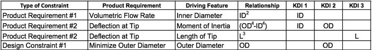
Table 1: Product requirements and design constraints
As can be seen in Table 1 above, ID is referenced as a key design input in both product requirements. This will result in dueling requirements. The same can be said for OD as it is referenced as a key design input in product requirement #2 and design constraint #1. The challenge for the design engineer is to find a range for ID and OD that satisfies both product requirements and the design constraint on the OD of the tube.
The Layout of the Skew/Limit Samples via Design of Experiments (DOE)
With the KDI features mapped against first principle equations as in Table 1 above, the next step is to create a summary table showing the KDI features with their nominal dimensions and upper and lower tolerance limits as in Table 2 below. The designer may gather these nominal dimensions and tolerance limits from a number of sources, including the Machinery's Handbook, past experience and knowledge, or a preferred supplier.
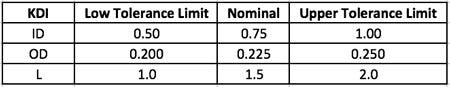
Table 2: KDI feature limits
With this table complete, the design engineer is ready to utilize a statistical software package, such as Minitab® 17 or JMP Pro®, to help plan the skew/limit samples. The term skew is leveraged from the drafting industry as each design is a design skew and we can show all the design skews in a simple table on the drawing. The term limit sample is used because the values of the skew samples come from the tolerance limits on the KDI features. We combine them in this paper as skew/limit samples.
For this part of the CFC process, the design engineer takes the KDI features from Table 2 and enters those KDI features as factors into the software's DOE planning tool. When prompted by the software for the low and high settings for the DOE, the design engineer enters the low tolerance limit and upper tolerance limit for each KDI feature from Table 2.
To demonstrate this, Minitab®17 was used to create a three-factor, two-level full factorial DOE with one center point. As can be seen in Figure 1 below, we used three factors (the KDIs ID, OD, and L) and each of them had two levels (low and high). Those low and high levels came from Table 2, which showed their low tolerance limit and their upper tolerance limit.
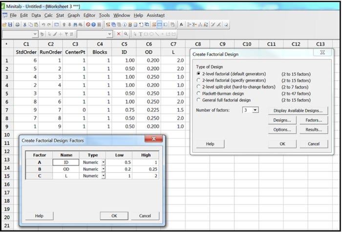
Figure 1
Once the skew/limit samples are defined in the statistical software worksheet, as seen in the Minitab columns C5, C6 and C7 in Figure 1 above, the design engineer can then cut and paste from the statistical software into Microsoft Excel®. Once in Excel, the design engineer can sort by column as seen in Table 3 below. Sorting makes the table easier to read later in the process.
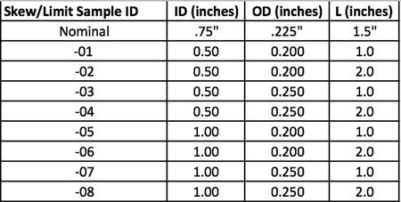
Table 3: Sorted by column
With Table 3 complete, the design engineer models the nominal geometry in the CAD software, inserts Table 3 on the drawing and the drawing is complete. The design engineer does not need to model each skew/limit sample separately in the CAD software for the CFC process to work; they simply need the nominal geometry shown in CAD form and all of the KDI features listed in table form. With the final drawing complete, the design engineer sends the drawing to their preferred supplier. The preferred supplier builds the requested quantity of samples for each of the design skews, labels the samples and sends the samples back to the customer. It should be noted, that if the supplier prefers to work directly from the customer CAD file, it might be beneficial for the customer to model each skew/limit sample in CAD and send separately to the supplier.
With labeled samples in hand, the design engineer tests each sample for the product requirements of volumetric flow rate and deflection at the tube tip. Since these skew/limit samples were set up via a DOE tool in a statistical software package, the design engineer now enters the data collected for the functional requirements back into that DOE layout and runs the DOE analysis.
If any of the three KDI features does not show as statistically significant against either of the product requirements, then the design engineer has the statistical evidence to demonstrate that that particular KDI feature should not be a critical feature moving forward. This is one of the key benefits of the CFC process as the team simply stops worrying about that non-critical feature for the rest of the project. It is important to keep in mind that it only takes a KDI feature to be statistically significant against one of the product requirements for that KDI feature to be confirmed as a critical feature for the rest of the project. For example, ID may be statistically significant for volumetric flow but not statistically significant for deflection at tube tip. In this case, ID would still be confirmed as a critical feature.
Enhancing the Design Process with Critical Feature Confirmation
By implementing the CFC process, product development teams can streamline the design and testing process of a new medical device, which in turn accelerates time to market and makes the world a better place for patients.
The benefits of the CFC process extend beyond the design team as well, with implications for quality and project management teams. The process answers many of their what-if questions with reliable, proven data. And this data can in turn be used with regulatory bodies as evidence during the approval process.
As design teams face continuing pressure to reduce iterations and design costs, they need a better way to identify which device features are critical and which are not. Adopting the CFC process helps alleviate these stresses by focusing attention on critical features that are confirmed to affect functionality. Simply put, the CFC process is a crucial tool in the product development toolbox.
For the CFC process to work best, medical device firms need to partner with suppliers that are capable of supporting such a strategic activity of the business. Lowell Inc. is a contract manufacturer that builds precision machined components and assemblies for the medical device industry. Lowell is here to help our customers in their journey to design and market patient-saving devices and we look forward to hearing the many success stories in the future use of the critical feature confirmation process at your firm.

Edward Jaeck is the vice president of operations at Minneapolis-based Lowell, Inc., a medical device contract manufacturer. He's a senior certified geometric dimensioning and tolerancing (GD&T) professional through the American Society of Mechanical Engineers (ASME) and a Six Sigma Black Belt. Reach him at [email protected].
[Image courtesy of STUART MILES/FREEDIGITALPHOTOS.NET. Figures and Jaeck headshot courtesy of LOWELL, INC.]
References:
1 Horton, H.L., Jones, F.D., Oberg, E. & Ryffel, H.H. (1996). Machinery's Handbook 25. Twenty-Fifth Edition. New York, NY: Industrial Press. pp. 216.
You May Also Like