Sign up for the QMED & MD+DI Daily newsletter.
Imaging Speaks Loudly to Medical Device Testing
FDA Guidelines can offer insight in employing x-ray inspection in development.
May 14, 2013
5 Min Read
.svg?width=850&auto=webp&quality=95&format=jpg&disable=upscale "Imaging Speaks Loudly to Medical Device Testing")
By Gil Zweig, President, Glenbrook Technologies
Over the years, FDA has issued a number of documents that provide guidance for industry and FDA staff, with sections that address the application of x-ray inspection procedures in the testing of medical devices. The particular focus of these documents has been on cardiovascular devices, which include intravascular stents and associated delivery systems.
Document number 1545, issued in 2010, addresses non-clinical engineering tests and recommended labeling for intravascular stents and associated delivery systems.
The issue of the radiopacity of stents is addressed in section B.14, with the recommendation that the manufacturer provide an indication of a stent’s radiological visibility. It says:
|
The three stages which FDA recommends evaluating radiopacity. |
“FDA recommends that you evaluate the radiopacity of your stent at the smallest diameter and the shortest length during the following stages in the life of the stent: Delivery; deployment if separate from delivery; [and] after implantation. Data to be provided indicating radiological visibility using animal or in vitro phantom implants.”
Meanwhile, document number 1717 addresses general considerations for animal studies for cardiovascular devices. In the section on “Post-Mortem Imaging and Assessment Methods,” it says about explant radiography:
|
Example of radiography in an explanted heart |
“Prior to preparing devices for histomorphometric analysis, you should consider whether an analysis of the structural integrity of the device would assist in the determination of device safety. For devices that are implanted in coronary arteries or intra-cardiac locations such as coronary artery stents or prosthetic heart valves, you should consider the use of device radiography in explanted whole hearts.”
Radiological Imaging Modalities Available
For radiological viewing, the x-ray image can either be exposed onto a photographic film or be converted to a video image. Two basic fluoroscopic modalities exist, which can be described as static imaging and dynamic imaging. Both depend on a scintillator to convert the x-ray to a light image. A flat panel imager is basically a scintillator coated onto a CCD array that produces static fluoroscopic images, or a series of still x-ray images.
Dynamic, or real-time, fluoroscopy produces x-ray movies. Dynamic imaging fluoroscopes employ a scintillator coupled to an image-intensifying device that amplifies the light image and presents it to a video camera for display.
Magnification fluoroscopy employs fine particle, high-resolution scintillators coupled to non-demagnifying intensifiers that produce high-resolution fluoroscopic images at relatively low radiation levels. These fluoroscopic images can then be magnified optically for video display. This process is now finding increased use in pre-clinical studies of medical devices because of the ability to rotate or deploy the device while recording the video. To see the video, click here.
Other imaging modalities include computerized radiography, where the x-ray image is stored on a storage phosphor and read out with a laser, and CT or computerized tomography, where the image is mathematically reconstructed from many measurements at the transmission value of a pencil beam of x-rays.
Evaluating Device Radiopacity
Different materials exhibit different radiopacity as a function of material composition (i.e. atomic weight) and thickness, as well as influenced by the anode voltage of the x-ray source. Note that an object of high radiopacity can veil the details of an object of low radiopacity, regardless of whether one object is in front of or behind the other.
|
|
A stent in radiography. | Close up of stent, showing a break. |
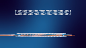
Stent development offers an example of designing devices used in angiographic procedures for x-ray inspection. The difference in radiopacity is seen in the fluoroscopic images of a nitinol (nickel-titanium) and stainless steel stent in a preserved rat. The nitinol stent has visibly less radiopacity than the stainless steel stent, requiring the nitinol stent to have platinum markers on the tips for fluoroscopic detection. Because radiopacity is a function of the atomic weight of the device’s constituent elements, the platinum tips, having higher atomic weight, add radiopacity.
In stent development, high-resolution magnification fluoroscopy also permits the observation and fluoroscopic video recording of the stent deployment as an x-ray movie. Stent wire breaks after fatigue testing can be detected with this method.
For this application, the detection of a break requires observing the stent with dynamic fluoroscopy as the stent is slowly rotated. The complete wire structure can be observed and recorded this way.
|
Voltages for different x-rays, from 20 kV to 80 kV. |
Conclusion
In performing radiopacity evaluation, it is important to note that the radiopacity of a device is influenced by the setting of the x-ray source anode voltage, which can range between 20 and 80 kV.
The FDA guidelines suggest the use of x-ray inspection for the determination of the radiopacity of intravascular stents and delivery systems.
The resulting images and their interpretation will depend on the methodology and x-ray systems that are used as well as an understanding of the factors that influence the appearance of the x-ray image.
Gil Zweig is president of Glenbrook Technologies, which has developed the magnification fluoroscopy x-ray technology presently in use at the FDA, the CDC and numerous medical device and small animal research facilities. He can be reached at [email protected].
You May Also Like