Sign up for the QMED & MD+DI Daily newsletter.
Calculating Factors of Safety for Package Burst and Creep Test Fixtures
TESTING A method for inflation seal strength testing employs flat restraining plates.
January 1, 1998
15 Min Read
.svg?width=850&auto=webp&quality=95&format=jpg&disable=upscale "Calculating Factors of Safety for Package Burst and Creep Test Fixtures")
A method for inflation seal strength testing employs flat restraining plates.
Testing flexible packaging for burst seal strength and creep resistance continues to be an important aspect in ensuring overall device integrity. An improved method of performing these tests involves the use of restraining plates to restrict package movement. Given the high pressures and forces used in such testing, the safe and effective design of these restraining fixtures is critical to protecting operating personnel. When equipment designers are determining appropriate construction of the plates, a factor of safety—the ratio of the allowable load on a structure to the actual load—must be calculated and incorporated into the process.
UNRESTRAINED TESTING
This article explains an approach that can be used to create safe and effective flat plate fixtures. Because of risks inherent in pressure testing, the author recommends that a knowledgeable engineering group determine the proper design criteria, materials, and processes for manufacture and maintenance of these fixtures. Selection of adequate factors of safety for fixture design must be based on the understanding of the specific application.
Burst seal strength and creep resistance tests are commonly used to minimize the time involved in obtaining quantitative values of flexible package quality parameters or to provide information about process control or performance. A burst test value is obtained by inflating the package at a uniform rate to its maximum pressure, which is indicated by rupture of one of the seals. A creep or creep-to-failure test delivers a constant inflation pressure to the package interior to measure the creep resistance of seals during a specified time period. These creep tests are considered analogs of differential pressures experienced by the package during sterilization or transport cycles.
Since the initial implementation of inflation-type seal-strength tests, most manufacturers have used them on packages that are not restrained in any axis and that therefore are not prevented from expanding. This technique, described in "ASTM F 1140-96, Standard Method for Failure Resistance of Unrestrained and Nonrigid Packages for Medical Applications,"1 is subject to variations in package geometry and material properties. In its essence, the method permits the package geometry to attempt to move into a balloon or membrane structure. While the inflation pressure is uniformly distributed in the package, the seal stresses generally are not, unless the package geometry is spherical, which is not common for medical device packages. As a result, packages with asymmetrical geometry will have varying stresses and deflection to rupture the seals. Most commonly, for example, rectangular packages with one long axis will rupture along this axis unless a manufacturing abnormality weakens the adjacent short-axis seals. Such long-axis rupturing is expected if each axis is considered a beam whose deflection is a function of its length and subsequent stress is highest at the point of maximum deflection. The seal stress can also be increased by the presence of geometry-related hoop stresses, in which forces are applied to the package's periphery. Furthermore, properties of the packaging material may affect test results when stretching or fracture of the films occur.
RESTRAINED TESTING
While unrestrained testing produces a reliable measure of flexible package strength and process operation, some manufacturers have found that restraining plate tests control the uniformity of applied stress at the seal and provide more consistent information about a package's minimum seal strength area. Restrained testing is characterized by the presence of a wall, force, or device that prevents the package from full expansion. Information on the precision and bias of the methodology is being compiled by ASTM committee F2.6 on flexible medical packaging.
Applying uniform stress to all three or four seals of a rectangular open or closed package is one aspect of evaluating seal strength. The uniformity of stress arises from the uniform geometry of the restrained seal around the perimeter of the package. An approximation of this geometry is shown in Figure 1. In an ideal model, the package film material is supported by the restraining plates that are rigid relative to the film. A relatively uniform radius (R) is then created at the seal with uniform force vectors being applied by the internal pressure (P). If for simplicity's sake we assume that only forces perpendicular to the seal (Fy) are acting to peel open the seal surfaces and the forces parallel to the seal (Fx) have no effect, then we can understand how uniformity of geometry and lack of hoop stress effects will provide more consistent seal strength results along the seal perimeter.
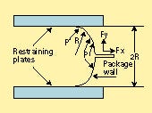 Figure 1. An approximation of the stress created by uniform seal geometry around the package perimeter (P =
internal pressure, R = radius, Fy = forces perpendicular to the seal, and Fx = forces parallel to the seal).
The use of restraining plate tests as part of the measuring process for burst seal strength and creep resistance tests is expected to grow. In anticipation of the method's increasing use, ASTM committee F2.6 is drafting proposed standards for restrained pouch and blister package configurations. However, there are concerns about the safe use of such restraining fixtures. The issues of fastener strength and proper materials selection for the plates must be addressed since significant forces may be created by using pressure sources and large-area bags.
The forces placed on the restraining plates are caused by the inflation pressure applied to the package and the package's area of contact on the fixture according to the following equation:
F = P x A
where F = force in pounds, P = applied pressure in pounds per square inch, and A = the area of contact in square inches. For example, a 5 x 5-in. bag at 3 psig at burst will apply 75 lb of equivalent force to each plate in a restraining fixture. For a 12 x 15-in. bag at 20 psig, there is an equivalent force of 3600 lb applied to each plate. These forces must be resisted by both the plates and their restraining fasteners.
PLATE FIXTURE DESIGN
When considering the construction of the restraining plate fixture, the designer must anticipate the largest loads expected, determine the fastening configuration of the fixture, and take into account the test operator's ease of use. Other aspects to consider include factor of safety, bolt size and material, effects of repeated loading (fatigue), plate thickness, allowable deflection, and maximum pressure. These are discussed below.
Factor of Safety. Before considering the bolt size and load relationship, a factor of safety should be chosen. Applying a factor of safety of 3.0 to 5.0 will usually be adequate, based on a well-designed fixture created by a knowledgeable engineering staff.
Bolt Selection. To understand bolt size requirements, consider a fixture with two plates that are bolted at the four corners and in the middle of the two longest sides. The shorter sides, where the package will be inserted, are left open. The minimum bolt size required to resist the applied load can then be calculated. Using six bolts with a 12 x 15-in. fixture with a 20-psig maximum working load, the total load is 12 x 15 in. x 20 psi = 3600 lb. Dividing the force over six retaining bolts yields 600 lb per bolt, and using the factor of safety of 3.0, the design load is 1800 lb per bolt.
For a common steel bolt, the allowable yield stress is defined by material properties and the stress area of the bolt. This enables the allowable load to be calculated by multiplying the allowable stress by the specified stress area.
Using the calculated load and applied factor of safety of 3.0, the bolt size with the minimum tensile strength nearest to and greater than the design load is 5/16-18 (Table I). This bolt has a minimum tensile strength of 2850 lb, whereas a bolt one size lower is below the design load requirement. The actual factor of safety is 2850/600 = 4.75. Even though this figure is greater than the original target, it is advisable to use it when also considering the fatigue life of the bolt under conditions of repeated loading.
Bolt Size | Stress Area | Minimum Tensile | Torque at | Preload |
|---|---|---|---|---|
10-32 | 0.0199 | 1092 | 41 | 655 |
1/4-20 | 0.0317 | 1750 | 53 | 1050 |
5/16-18 | 0.0522 | 2850 | 107 | 1710 |
3/8-24 | 0.0876 | 4800 | 215 | 2880 |
1/2-13 | 0.1416 | 7800 | 468 | 4680 |
Table I. Bolt size and allowable loads for commercial steel bolts with a yield strength of 55,000 psi.2
Fatigue. The engineering literature indicates that bolts that are properly tightened (and therefore have adequate preload) and subject to variable loads that are less than the preloads will have virtually infinite life. Consider a 5/16-18 bolt that, as indicated in Table I, has a preload of 1710 lb at 60% of its yield strength. If the bolt is subjected to a repeated load of 600 lb, it will have a life of 1 million to 10 million or more cycles with a factor of safety of 2.85. This calculation is also predicated on the selection of bolt materials. If a higher-grade bolt such as a grade 5 or 8 is used, then an even greater factor of safety is achieved. Since bolt quality can vary, the selection of higher-grade bolts will provide greater assurance of meeting the design criteria.
Table I indicates the torque required to achieve a preload of 60% of the yield strength of the bolt. Proper preloading assumes that the material surfaces are smooth and uniform, that there are no gaskets or compliant washers to prevent substantial contact of the bolt with the plates, and that the applied preload is maintained. If the preload is lost, the factor of safety for repeated loading is lost, and fatigue failure may become an issue.
Plate Selection. The plate thickness is chosen based on several factors, including safety, material, size, and restraining conditions. From standard engineering references such as Formulas for Stress and Strain,3 formulas can be found to approximate stress and deflection in the fixture plates for given test pressures and pouch sizes. However, these formulas consider only standard boundary and loading conditions and should be used only as a guide to and approximation of real-life designs. For example, our model assumes that the plate edges are held on two sides, not four. A change in boundary conditions may affect the choice of the factor of safety used in the following calculations. A more sophisticated finite-element analysis of specific design configurations can be conducted with appropriate computer and engineering expertise.
The designer of the fixtures must use caution in applying formulas based on idealized design equations. Because most real-life designs do not precisely fit the engineering model equations, it is advisable to consult with a knowledgeable engineering professional to confirm the safety aspects of these mechanical designs.
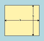 Figure 2. The plate's length (a) and width (b) dimensions are used to determine the basic strength and deflection of the fixture.
A simplified approach to estimating the basic strength and deflection of the fixture is to use the standard plate deflection formula for simply supported plates of thickness (t) and dimensions a (length) and b (width) (Figure 2). The "simply supported" assumption allows for rotating edges during deflection and represents a maximum case compared to a "fixed edge" assumption. The stress and deflection, respectively, can be calculated as follows:
S = ßwb2/t2 and Y = αwb4/Et3
where S = stress, Y = deflection, and both are maximum at the center of the plate. α and ß are empirically derived constants that are a function of dimensions a and b. The material factor for rigidity of the plates is Young's modulus (E), and the load w is in pounds per square inch. The load is assumed to be uniform over the entire surface. Table II shows the relationship of α, ß, and dimensions a and b.
a:b | α | ß |
|---|---|---|
1.0 | 0.0444 | 0.2874 |
1.2 | 0.0616 | 0.3762 |
1.6 | 0.0906 | 0.5172 |
2.0 | 0.1110 | 0.6102 |
5.0 | 0.1417 | 0.7476 |
Table II. The relationship of coefficients α and ß to a and b dimensions.
The designer must consider first of all the safety of the design by choosing a plate thickness (t) and its material through determination of its stiffness factor E and its yield strength. Table III lists the approximate modulus and yield strength for four common materials: stainless steel, aluminum, acrylic, and polycarbonate polymers. The most rigid material is steel, the weakest are acrylic and polycarbonate polymers. Generally, a high-quality aluminum is a better choice for strength, deflection, weight, and machinability. However, steel may be required for larger plates or higher pressures. Plastic should be avoided because of its inadequate strength and stiffness properties, as well as its relaxation properties under loads from the restraining bolts.
Material | Young's | Tensile Yield |
|---|---|---|
Acrylic | 0.38 | 8,000 |
Polycarbonate | 0.30 | 7,000 |
Aluminum (2024-T4) | 10.6 | 42,000 |
Stainless steel (304) | 28 | 30,000 |
Table III. Approximate modulus and yield values for materials commonly used for plate fixtures. 2,4
Figure 3, using an assumed value of w = 20 psi, shows data on a 6-in.-wide plate fixture and demonstrates the relationship of a, b, and t, related to deflection. The same data are used in Figure 4 to show the relationship of yield stress to a, b, and t. Again, using a factor of safety in the design is prudent. An indication of a stress factor of safety of 2.0 is shown in Figure 4. By decreasing the allowable stress from the expected yield stress of 42,000 psi to 21,000 psi, the plate thickness is increased for the factor of safety.
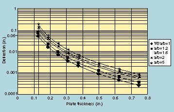
Figure 3. Deflection versus plate thickness for a 6 x 6-in. aluminum plate fixture. The load is assumed to be 20 psi.
Figure 4. Stress versus plate thickness for a 6 x 6-in. aluminum plate. By decreasing the allowable stress from 42,000 psi to 21,000 psi, the plate thickness is increased for a factor of safety.
In this example with a 6 x 6-in. plate of 2024 -T4 aluminum with an assumed pressure contact area over its entire surface, a minimum thickness of 0.125 in. would be suggested since its a/b = 1 and its calculated stress of 13,250 psi is below the yield stress with a factor of safety.
Deflection Allowance. Another consideration for the designer is the allowable deflection of the package and fixture. Returning to Figure 3, the deflection of the plate at 20 psi when the plate thickness is 0.125 in. can be found from the chart as 0.06 in. For the most consistent test results, the package and fixture should deflect a minimal amount to maintain the geometry of the seal forces. While this consideration is in the hands of the designer, a maximum deflection of 0.03 to 0.06 in. at the plate center is, in practice, very noticeable. In this case, selection of a thicker plate will lower the visible deflection as well as provide a greater factor of safety in the design. The deflection and related burst seal strength pressure can be influenced by the plate separation distance 2R seen in Figure 1. Larger separations will yield lower average burst seal strength pressures and thereby lower both the stress and deflection values. Required bolt sizes and loads are calculated and designed as previously discussed.
Maximum Pressure. Finally, the maximum pressure capability of the test instrument should be evaluated for the 0.125-in.-plate-thickness fixture in the same way as the working pressure was evaluated. This evaluation indicates that if a product package were able to withstand this maximum instrument pressure, or if accidental application of the maximum instrument pressure were applied to the fixture, then the fixture would be of adequate strength.
For a test instrument with a maximum capability of 50 psig, when w = 50 psi, b = 6 in., a = 6 in., a/b = 1.0, and t = 0.125 in., the stress is calculated to be about 33,000 psi for the plate, a figure that is below the maximum yield of 42,000 psi for this particular aluminum alloy and temper. The bolt load is 450 lb per bolt for a four-bolt pattern. Referring to Table I, the use of 1/4-20 steel bolts would provide adequate strength and a factor of safety of 1750/450 = 3.9. This may be a larger and more prudent bolt size selection than previously calculated for the working pressure design criteria.
CONCLUSION
As plate dimensions grow, so do the stress and deflection. Careful planning must be used in the design of the restrained plate fixture to ensure the safety of its use in its maximum loading condition as well as in its expected operating condition. A prudent operating facility will also observe safety precautions such as use of safety glasses and protective shields for operating pressurized equipment.
In practice, most porous packages made of paper or Tyvek with peelable adhesives will burst in the 1—3-psi range. In these cases, using metal plates and properly designed bolts will provide adequate protection against catastrophic failure of the fixture. However, with nonporous materials, more attention must be paid to expected seal-burst pressures, since some heat-welded seals may yield at burst pressures of 50 psi or more.
The practical designer, in conjunction with knowledgeable engineering consultation, will use conservative design criteria and will select materials with known properties. By employing thicker plates and larger fasteners when necessary, a fixture's factors of safety can be increased.
REFERENCES
1. "ASTM F 1140-96, Standard Test Method for Failure Resistance of Unrestrained and Nonrigid Packages for Medical Applications," 1997 Annual Book of Standards, vol 15.09, West Conshohocken, PA, American Society for Testing and Materials, 1997.
2. Daniels DB (ed), Society of Manufacturing Engineers, Tool and Manufacturing Engineers Handbook, 3rd ed, New York, McGraw-Hill, 1976.
3. Roark RJ, Formulas for Stress and Strain, New York, McGraw-Hill, 1965.
4. Harper CA (ed), Handbook of Plastics and Elastomers, New York, McGraw-Hill, 1975.
Stephen Franks is executive vice president for T.M. Electronics, Inc. (Worcester, MA).
Copyright ©1998 Medical Device & Diagnostic Industry
You May Also Like