Issues in Hermetic Sealing of Medical Products
Medical Device & Diagnostic Industry MagazineMDDI Article IndexOriginally Published January 2000MANUFACTURINGEnsuring hermeticity in a medical device is a function of materials choice, final seal design, fabrication processes and practices, and use environment.
January 1, 2000
Medical Device & Diagnostic Industry Magazine
MDDI Article Index
Originally Published January 2000
Ensuring hermeticity in a medical device is a function of materials choice, final seal design, fabrication processes and practices, and use environment.
Medical devices and instruments are generally considered among the most reliable assemblies that can be manufactured. One reason for this is the typical quality of the hermetic seals in such products. The achievement of hermeticity is the process by which the internal environment of the critical components is made secure from invasion and contamination from the external environment, and is a function of both the bulk permeability of the chosen materials and the seal quality. The sealing process can be as simple as using a compressed gasket to prevent incidental fluid exposure or as complex as a full-penetration fusion weld for bioimplants such as pacemakers.
Hermetic seals can be characterized by a variety of test methods, from standard pressure-decay or bubble-emission tests to sophisticated mass spectrometer or radioactive analyses. Because all materials and all welded or joined assemblies will leak to some degree—whether by permeation through the bulk material or along a discontinuity path—the degree and measure of hermeticity is a function of materials choice, final seal design, fabrication processes and practices, and the use environment.
The need for hermeticity was originally driven by sophisticated military electronic applications. System failures in both electronic and mechanical systems had been traced to the ingress of moisture, which can cause dielectric breakdown, corrosion, and loss of insulation resistance between conductors. To eliminate these failure modes, hermetic packaging materials and processes were developed. In this case, hermetic refers to packaging technology designed to keep moisture from condensing inside the enclosure during exposure to the service environment.
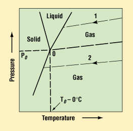 Figure 1. Triple-point diagram for water. The solid lines separate regions indicating the physical state of water as a function of temperature and pressure.1
The ability of moisture to condense is a function of the dew point—that is, the moisture content, pressure, and temperature that allow liquid droplets to form or condense. The triple-point graph for water is shown in Figure 1.1 Water can exist as solid, liquid, or gas, depending on temperature and pressure. The shaded areas represent the form the water can take for any given combination of temperature and pressure. The nomograph in Figure 2 can be used to predict the water content for any given conditions.1 For example, it can be seen that at 1.0 atm and 0°C, the moisture content needed for liquid droplets to form is 6000 ppm. At levels below this percentage of water vapor, liquid drops will not be able to form. Hence, most materials and sealing processes are selected to keep the internal package environment at or below 5000 ppm of moisture for the life of the device.
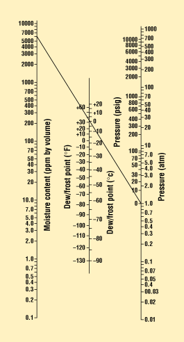 Figure 2. Dew-point nomograph that correlates pressure, temperature, and water content. (As shown, at 1.0 atm and 0°C, the dew point is 6000 ppm of water.)1
In most early electronic systems, hermeticity was achieved by using a metal enclosure and glass-to-metal seals with a leak rate of less than 10-8 He/cm3/sec of He at STP. It was thought that, at this low level of leakage of a small atom such as helium, the exclusion of moisture and its corrosive effects would be assured.
Hermeticity has been defined in various ways; for example, as "the state or condition of being airtight,"2 or, alternatively, as "sealed so that the object is gastight."3 However, as stated earlier, all materials leak, or more accurately, all materials are permeable to some gas to some degree. Welds and joints between materials may have preexisting cracks or pores that provide a leakage path. The total "leak" is thus a combination of both the bulk permeation through the material and any open leak paths that lead directly from the internal to the external environment. Therefore, the process of ensuring hermeticity can be described as the selection of materials and manufacturing techniques that yield an enclosure that has sufficient material thickness to impede the diffusion of gas into the internal package cavity and that can be sealed without pinholes, cracks, or other discontinuities that provide a direct leak path.
In the medical industry, the choice of enclosures can span a large range of materials and involve numerous joining processes. For implantable devices, the materials are often metals such as nitinol, platinum, or MP35N or other stainless steels. Other materials may include ceramics (Al2O3) and many plastics—for example, polyurethanes, silicones, and perfluorinated polymers. Similarly, joining processes vary from the use of adhesive sealants and encapsulants to fusion methods such as laser-beam welding or reflow soldering, or solid-state processes such as diffusion bonding. Plastics and laminates can be joined by a variety of methods including impulse, heated-platen, radio-frequency (RF), dielectric, and ultrasonic sealing, to name a few.
The selection of an appropriate enclosure material and sealing process alone is not sufficient to guarantee that the internal moisture content in a device will remain low enough to preclude droplet condensation or transfer of materials through the wall thickness. The internal device materials often add to the vapor pressure inside the enclosure, and can alter the leak performance. For instance, conductive epoxies, conformal coatings, silicones, and Teflon can all outgas water vapor. Table I shows an example of the water-vapor content within an electronic package as a function of cure time and temperature.4 Control of these internal sources of contaminants is also required for long-term reliability.
Cure Time (hr) | 150°C (ppm) | 200°C (ppm) | 250°C (ppm) |
1 | 15,000 | 14,000 | 10,000 |
10 | 5,000 | 1,000 | 50 |
100 | 500 | 200 | 10 |
Table I. Water-vapor content of glass-sealed electronic package.4
The sections of this article that follow review hermeticity test methods and the types of hermetic seals that can be made within the broad scope of acceptable medical materials and processes.
MEASURING HERMETICITY
Hermeticity is commonly measured by dye-penetrant, bubble-emission, pressure-decay, microbial-ingress, radioactive, and mass spectrometer systems. All of these techniques are commercially available and can be used to detect leaks. Some—like the bubble and dye methods—can pinpoint the exact location of a leak. Others only detect the summation of all the leaks present and are used in go/no-go inspections.
Regardless of the measurement system, the basic approach is the same. A pressure difference is developed between the internal volume of the package and the external environment. This pressure gradient causes gas or liquid to diffuse or leak through the bulk material or seal area. The material "leaking" through to the external environment is then sensed. In the case of radioactive, microbial, and mass spectrometer methods, the test can be both qualitative (what is leaking) and quantitative (how much is leaked). For the purpose of this article, all leak rates refer to helium rates measured at 1 atm pressure differential and 20°C and are defined as helium atoms per cubic centimeter per second (for example, 10-5 He/cm3/sec (STP)).
More thorough discussions of leak-rate measurement are provided in a number of sources and will not be covered here. However, a few key points are highlighted by the schematic in Figure 3. The permeation of materials through the barrier is a function of the concentration of the diffusing material, its affinity for the matrix (chemical adsorption), and the physical size of the molecules. The major point is that just because a joint leaks helium at a rapid rate, the same joint may not leak water vapor because of pore size or chemical binding of the moisture in the base material. This is also true for direct leak paths, for which the path may be so tortuous and small in diameter that the leaking molecule may not physically fit. In another case, the pressure drop across the leak path may be so minimal that the leak becomes diffusion limited, with the added effects of absorption of the material to the walls of the leak channel. In these cases, the package may actually be "hermetic" according to the needs of the client, even though a leakage path exists.
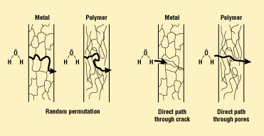
Figure 3. Schematic of typical leaks. Leakage can occur because of permeation through the bulk material or as the result of a direct leak path from a crack or pore.
HERMETIC SEALING IN METAL PACKAGING
Metal packaging is favored for most high-reliability systems because of the impermeability of bulk metals. Even thin layers of metals such as nickel, gold, and aluminum are sufficient to impede the transfer of gas molecules across a membrane. Common housing materials are Kovar, MP35N, stainless steels (304 and 316 grades), and titanium. Two types of seals are common in these packages: feed-through seals of glass or ceramics, and final cover seals that are fusion welded, brazed, gasketed, or adhesive bonded.
Feed-through seals are the interconnection of external electrical leads through the package wall to the internal cavity of the package. The lead is often Kovar or a similar low-expansion metal chosen for its coefficient-of-expansion match to the glass material that forms the seal. A glass or ceramic bead is placed on the lead and heated in a controlled furnace environment. The glass flows and forms a seal between the lead and housing wall as shown in Figure 4. Glasses and ceramics are especially good as seals because of the low moisture permeability of these materials after firing.
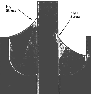 Figure 4. Stress-field model of glass-to-metal seal after cooling to room temperature.
During firing, moisture can be a problem, as noted by Shukla and Mencinger, who studied the moisture evolution of sealing glasses.5 Their evaluation indicated that three distinct stages of moisture outgassing occur. First, during approximately the first 30 minutes there is a loss of absorbed moisture on surfaces, followed by a second period of up to about 35 minutes when there is a loss of internal moisture as the glass softens, and finally a third period of from 35 to 50 minutes when a loss of chemically bound moisture occurs. Even assuming that pores and internal moisture have been controlled, glass seals can be prone to physical leak paths. Glass seals fail hermeticity tests for physical leaks for the following reasons:
Poor surface preparation. The metal package should have a proper oxide finish that is both adherent and of the proper thickness. Too thick an oxide layer can be porous or poorly adherent to the base metal.
High stress in the glass leading to glass fracture. Seals are generally chosen as either matched or compression seals. In compression seals, the glass is kept in direct compression because of the higher expansion coefficient of the metal compared with the glass. With this configuration, as the metal housing cools to room temperature from the glass's softening point, the glass is compressed. This constitutes an excellent seal for many applications, but may not have the best thermal cycle performance, especially with low (below –55°C) temperatures. In matched seals, some differential still exists in the joint and can crack the glass or cause the glass to pull away from one of the metallic surfaces. Matched seals are often better for wide swings in service temperature because of their lower thermal-cycle stress at low temperatures.
Mechanical damage to the pin caused by bending the pin over. The bending stress often cracks the glass or causes the metal to pull away from the glass.
Mechanical damage to the glass. The glass can have a positive or negative meniscus as it wets on the housing wall or lead material. Positive-meniscus joints can be easily damaged, since even minor flexing of the lead can fracture the thin glass that has wicked up the lead.
Most package and header suppliers are well informed on these basic failure mechanisms and can design a feed-through system to meet client needs.
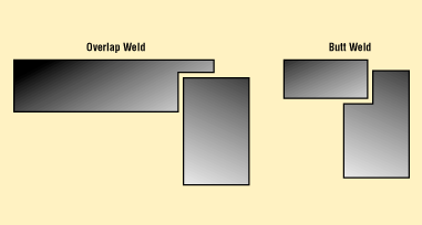
Figure 5. Both overlap and drop-in (butt-weld) cover joint designs can be hermetic, with minimal penetration. (Recommended penetration is 0.010 in. minimum for laser welds.)6
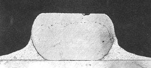 Figure 6. Joint area indicating reflow of solder by resistance heating process.
The final package seal usually consists of a metallic cover or lid that is joined to the top edge of the package. Covers can be a simple overlap joint or can drop into a recess, as shown in Figure 5.6 The cover-to-package seal can be accomplished in a variety of ways, including the following:
Brazing or soldering. In this method, a material with a lower melting point (below the melting point of the base metals) is added to the joint and reflowed in place. Among such materials are tin-lead, gold-tin, and copper-silver alloys. Common reflow methods include rapid infrared heating using quartz lamps or parallel-resistance seam welding set up to reflow the plated surfaces. An example of a resistance seam—soldered enclosure is shown in Figure 6. Note that the seal area is very narrow; its integrity is a function of the plating adhesion and reflow and wetting dynamics.
Laser welding. In this process, a focused spot of laser energy is traversed along the seam to fuse the cover to the housing. Laser welding is thus conduction limited and melts only a narrow zone of material. The zone adjacent to the fusion zone is referred to as the heat-affected zone (HAZ). In this area, fusion has not occurred but the thermal exposure has been high enough to cause a change in the microstructure of the grain.
Cover-to-package joints are not typically prone to permeation leaks, but rather to direct leaks caused by cracks or pores. However, permeation leaks are possible in thin materials that have been fully annealed. Figure 7a shows a thin sheet of 316L stainless steel in a half-hard condition. The grains are fairly small and several grains are required to fill the total thickness of the sheet. Figure 7b shows the same sheet in a fully annealed condition. In this case, some grains are large enough to allow a single grain boundary to traverse the sheet thickness. These boundaries have been found to leak helium in the 10–5 to 10–8 range.
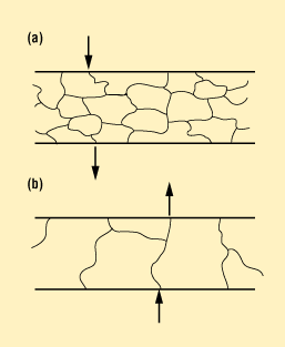 Figure 7. (a) Thin-sheet 316L stainless steel in half-hard condition, showing small grain size. (b) Thin-sheet 316L stainless steel in fully annealed condition, showing large grain size and locations where grain boundary has traversed the sheet thickness. These grain boundaries can be permeable to helium in a standard leak test.
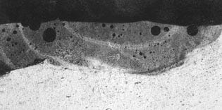 Figure 8. Weld porosity in an Nd:YAG laser weld of an aluminum housing using an aluminum filler alloy.
Figure 8 shows a laser-welded aluminum housing that features enclosed porosity. If not controlled by laser welding parameter selection and setup, these pores can provide a direct leak path. Soldered and brazed seals can be prone to porosity, to entrapped flux, or to developing cracks after environmental exposure. These cracks can be built in by the cover-to-housing design, especially when laser welding. Figure 9 details the built-in or intrinsic crack that can result during welding of an overlap cover design.
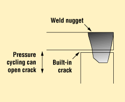 Figure 9. An overlap weld design can build in a crack that can open due to a package's internal pressure.
HERMETIC SEALS IN PLASTICS AND LAMINATES
Some would argue that a hermetic seal cannot be made in polymers because of the inherently high permeability of these materials to many gases. Figure 10 indicates the typical permeability of many common classes of materials. Many plastics and laminates, however, can easily meet a common definition of hermetic that specifies helium leak rates measured in the 10–1 to 10–5 range.
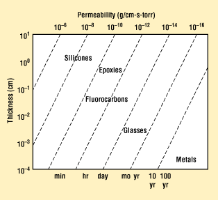 Figure 10. Permeability chart for common classes of packaging materials.
Laminate designs are widely used in medical and food packaging, with excellent results. These laminates are multilayered structures with materials specifically chosen to achieve a seal or barrier. Most laminates have a polyethylene layer that forms the adhesion layer at the joint interface. Other layers may include metal foils such as nickel or aluminum as moisture and oxygen barriers, as shown in Figure 11.
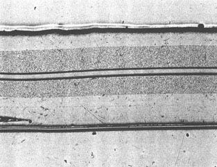 Figure 11. Typical laminate structure showing the seal layer, peelable layers (note crack at lower left), and internal barrier layers (shaded regions).
The leak rate measured in polymeric package designs is a reflection of both permeation and direct-path leaks.7,8 Direct-path leaks occur for various reasons, many of which can be traced to the sealing process. A variety of methods are used to seal laminate-type packages—including hot plate or hot bar, RF dielectric, infrared, ultrasonic, and even CO2 laser—and in all of these processes, the same set of events must occur. That is, melt zones are first produced and then forged together to allow the polymer chains to cross the interface and form a bond. Package leaks can occur as a result of circumstances that include the following:
Poor uniformity of the heat-source application. In some cases this is due to cooling of the heater element from material that contaminates the plate. This can be a drop of material from a filling operation or other debris. An example of this is shown in Figure 12, which shows a leak path that has traversed the seal area of a plastic package.
Bubble and pore formation. During heat application, some materials are prone to foaming. This can occur if the plastics have not been properly dried prior to welding. Also, during the application of heat, the water can boil, causing bubbles at the interface.
Poor control of the melt zone. In plastic welds, heat is applied to cause controlled melting of a narrow zone of material at the joint interface. After the melt zone is developed, forging pressure must be applied to allow interdiffusion of the polymer chains to form a seal. Improper control of the melt zone can result in a poor seal if the melt zone is not properly compressed or, more commonly, if the zone is overcompressed and the molten plastic is completely squeezed out. In the latter case, cold material from the HAZ is in the interface and a poor seal will be created.
 Figure 12. Dye penetrant indicating a failure zone in a plastic seal.
Given proper selection of materials and sealing method, effective seal design in polymeric packages can be achieved. Most good designs allow the forging pressure to form a bead of melt at the joint, and feature a long, tortuous bond line. With a long bond line, any leak path along the interface of the seal will be longer than the permeation path through the bulk material. Furthermore, with long seal areas, the chance of entrapped porosity breaching the entire seal is remote.
CONCLUSION
Hermetic packages for medical devices can be developed using either polymeric or metallic enclosure materials. The leak rate for typical packages will be 10–1 to 10–5 He/cm3/sec for polymeric systems; metallic packages can achieve rates of 10–5 cm3/sec or better. Such a leakage measure is a function of both the bulk material permeation and the seal integrity. Permeation of materials through the bulk is a function of chemistry and the laws of diffusion, whereas direct leak paths are more a function of pressure differential. Seal integrity can often be traced to the quality and control of the sealing process, especially control of the melt zone. Finally, hermeticity can be measured by a variety of methods, from simple pressure decay to sophisticated radioactive tracer systems.
REFERENCES
1. ASM Electronic Materials Handbook, Packaging, Vol. 1 (ASM International, 1989).
2. Webster's New Collegiate Dictionary (Springfield, MA: G and C Merriam, 1980).
3. R Tummala and E Rymaszewski, Microelectronics Packaging Handbook (New York: Van Nostrand Reinhold,1989).
4. RW Thomas, "Moisture, Myths, and Microcircuits," in IEEE Trans. on Parts, Hybrids and Packaging (1976), 167—171.
5. R Shukla and N Mencinger, "Moisture Evolution Analysis of Sealing Glasses Used in Integrated Circuit Packages," Electronic Materials 14, no. 4 (1985): 461–471.
6. K Ely, "Strength and Residual Stress in Laser Welded Aluminum Modules," in ISHM Conference Proceedings (1994).
7. D Morton, "Container/Closure Integrity of Parenteral Vials," Journal of Parenteral Science and Technology 41, no. 5 (1987).
8. JR Robinson, Advances in Parenteral Sciences (New York: Marcel Dekker).
Kevin Ely, PhD, is technology team leader in microjoining and plastics at the Edison Welding Institute (EWI; Columbus, OH). His areas of interest include hermetic sealing of ferrous and nonferrous electronic packages, thermal-stress management and evaluation, and design and process optimization using design of experiments and statistical evaluation. He holds a doctorate in materials engineering science from Virginia Polytechnic and State University. EWI provides practical welding and joining solutions through technical assistance, contract research, consultancy, and training.
Return to the MDDI January table of contents | Return to the MDDI home page
Copyright ©2000 Medical Device & Diagnostic Industry
You May Also Like


