Overmolding: A Multifaceted Medical Device Technology
Medical Device & Diagnostic Industry Magazine MDDI Article Index
January 1, 2006
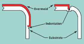
Medical Device & Diagnostic Industry Magazine Originally Published MDDI January 2006 COVER STORY: MOLDING More than simply providing a soft-touch surface, overmolding can increase device functionality and add value. By Michael Hansen Overmolding, an injection molding process, has drastically changed the aesthetics, design, and functionality of consumer products over the last decade. It is increasingly finding its way into the medical market as device makers realize its potential benefits. Although known for creating texture, commonly called soft touch, the process offers much more, including ergonomics, two-color aesthetics, brand identification, and property modification. The process can add functionality to a product (e.g., noise and vibration dampening, waterproofing, and shock absorption) and increase a product's value. Overmolding falls into the broad category of multimaterial molding, along with coinjection, two-shot, and sandwich molding. The basic premise of multimaterial molding is to take economical advantage of two or more materials with uniquely different properties by incorporating them into a single molded component. In this article, the first material shot is referred to as the substrate or substrate material, the second material as the overmold or overmolded material. Overmolding Options In overmolding applications, an overmold is injection molded around, over, under, or through a substrate material to complete the final part. This injection can be done with a multishot process or by insert molding. Usually, the overmolded material is an elastomeric resin. Multishot Process. Multishot molding is a good choice for medical devices if the configuration of the overmold permits it. The process requires a special press with two or more barrels so that different resins can be shot into the same injection molding tool. The barrels, arranged parallel to each other or in an L configuration, feed resin through common or separate injection points into the tool. When one common injection point is used, the process is called coinjection, and the result is a composite part in which a skin encapsulates a core resin. Separate injection points result in an overmolded part, which is produced by molding one component on top of the other, creating a layered structure. But multishot molding is not possible for all products. The required volume for the overmold must be able to be created by moving a slide or by rotating the mold core to another mold cavity. Another option involves shuttling the mold core to another press. Insert Molding. A product such as a completely overmolded handle would require insert molding. To be completely overmolded, a substrate must be taken out of the tool and placed into a different core and cavity to create the volume for the overmold material. During this process, a separate tool should run in the same or a different-size press (depending on shot size). Usually, the overmold portion of a part is significantly smaller than the substrate. Preheating the substrate might be necessary to bring its surface temperature closer to the melt temperature of the overmold, so as to reach optimum bond strength. In-Mold Assembly Sometimes overmolding is called in-mold assembly, since the resulting part essentially assembles two materials rather than creating a layered structure. Both individual components and assemblies can be overmolded. But regardless of the application, achieving a mechanical or chemical bond between the substrate material and the overmolded component is crucial. Multimolding Considerations The melt temperature range of the overmold resin, in general, should be in the same range as the substrate to enhance bonding. If the melt temperature of the overmold is too low to melt the surface of the substrate, the bond can be weak. However, if the melt temperature is too high, the substrate might soften and distort. In extreme cases, the overmold can penetrate the substrate, resulting in a rejected part. Choosing compatible materials is critical to ensuring a good bond. In general, compatible materials are of similar chemistry or contain compatible blended components. When the substrate and overmold materials are incompatible, a mechanical interlock can often replace the chemical bond. Of course, there are common problems in any multimaterial injection molding process. Most common are inadequate chemical or mechanical bonding between the polymers, incomplete filling of one or more components, and flashing of one or more components. Shot-to-shot consistency of the injection molding machine is a critical factor. And the ratio of the shot size of the barrel to the shot size of the overmold application is an important element in molding quality parts. Although this ratio is critical in all molding operations, it is especially important when overmolding a substrate. The shutoff, which functions as a dam to seal off the overmold, is more difficult to establish between hard metal and more-flexible plastic surfaces than it is with metal-to-metal surfaces. Selecting the Material A number of factors drive the material selection process for the overmold resin. The properties of the substrate material drive some requirements, while the performance profile for the application determines others. Such factors include the following: • Chemical resistance (cleaning requirements and others). • Flame retardancy (compliance with ecological labels and others). An ecological label is a seal or logo that indicates that a product meets a set of environmental or social standards. • Abrasion (to avoid denting and loose particles). • Shore hardness (soft touch and others). • Medical specifications (FDA, USP Class VI, ISO 10993, and biocompatibility). • Sterilization (steam, gamma radiation, etc.). • Impact resistance (structural requirements). • Melting point (to fall within temperature range required for the application without softening or distortion). • Bond mechanism (mechanical interlock with substrate for incompatible materials, or chemical or adhesive bond with substrate for compatible materials). In the last 5–8 years, the range of overmold materials has expanded to include many classes of elastomeric resins. Such resins include thermoplastic polyurethane (TPU), styrene-ethylene/butylene-styrene copolymer (SEBS), copolyesters, copolyamides, thermoplastic rubber (TPR), and thermoplastic vulcanate (TPV). The traditional material of choice was a modified polypropylene-based resin with the ability to adhere to a polypropylene substrate. These materials cover a wide range of Shore hardnesses. As a general rule, the harder the material, the less abrasive it will be. Texture will influence this property as well. Minimal abrasion is desirable because it translates into less weight loss during resistance testing. For example, if a sample is tested with a spinning grinding wheel, the weight loss resulting from a material with a harder durometer is less than that with softer resins. SEBS resins allow for very low durometers, even less than 30 Shore A. For TPU resins, the lowest achievable durometers are around 60 Shore A, which is the Shore hardness of the human hand. In the past, reducing durometers was typically accomplished by adding plasticizers or mineral oil. However, additives can leach out during cleaning procedures or field use. In medical applications, this leaching out, or blooming, is not acceptable. The development of a portfolio of overmold resins brought additional substrate possibilities, including acrylonitrile butadiene styrene, polycarbonate, and nylon. This much broader range of materials offers many opportunities for soft-touch design applications. But the new materials also present more challenges to overcome for adhesion, part design, and tooling. Tooling Considerations Shutoff design, gating, venting, and texture are key considerations when designing tooling for overmolded parts. The design of the shutoff between the substrate and overmold is critical to adhesion. A gradual thinning, or feathering, of the overmold should be avoided. Thin layers of overmold will likely result in poor adhesion, later delamination, and edge curling. A good shutoff design features a sharp transition between the overmold and substrate. The indentations on the substrate parts in Figure 1 illustrates such a design.
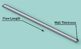
Gate design is also important for a successful overmolding application. The flow-length-to-wall-thickness ratio is critical for adhesion. As a rule of thumb, the ratio should not exceed 150:1. In new tooling developments, the ratio should be kept to around 80:1. Figure 2 illustrates the flow-length-to-wall-thickness ratio. To keep the flow length as short as possible, the gate should be located in the thickest wall area. Gate sizing is a function of the class of TPE. Some materials, like TPU, require bigger gates to compensate for higher viscosity and to avoid material degradation due to shear. Others, like SEBS materials, require more shear to achieve optimal flow. A good practice is to start with small gates, which can be opened up after an initial sampling. Like gate design, venting plays an important role in achieving good adhesion to the substrate. Air entrapment is a big problem for bonding. It generally results in poor adhesion and short shots at the end-of-fill locations. Vent depths are critical to avoiding flash. Depending on the viscosity of the overmolding material, the vent depth should be between 0.0005 and 0.001 in.
For certain part designs, a cosmetic surface texture can be helpful with part release on ejection. Most TPE-type materials tend to stick to mold surfaces because of their affinity for metal or because a vacuum is created between the overmold and the mold surface on the tool opening. The forces created by sticking can significantly affect material adhesion, since the chemical bond is still developing in many of the materials after a part is ejected. For the resulting product, that means the parts have to be handled carefully. If any qualifying test for bonding is required, the test should be performed after a 24-hour waiting period, allowing the chemical bond to fully develop. Sticking can also be a problem if there is insufficient draft when surfaces are parallel to the direction of tool opening. Materials like TPU require as much as 5Þ–6Þ of draft. Plating of the tool is also helpful for part release. The type of texture selected also deserves careful consideration. Texture influences both the soft touch and feel of the overmold, as well as the wall thickness of the overmolding application. The correct combination of wall thickness and texture helps achieve the application's desired properties. Usually, the lower the durometer measurement, the softer the material. Texture minimizes injection molding flaws and enhances the feel of the part. The part feels softer to touch than the durometer actually measures, meaning the texture results in a lower perceived durometer. Application Examples
Surgical Instruments. Figure 3 illustrates overmolding with the insert molding process. The process was performed by placing a machined-metal component (in this application, the substrate) into the tool and overmolding a portion of the metal component with an overmolding resin. It is important that the metal component be placed securely into the tool and shutoffs to prevent the overmolding material from creating a flash condition. In this case, a mechanical rather than chemical bond between the metal component and overmolded resin was used.
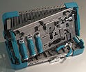
Figure 4 is a close-up of the substrate handles before the second overmolding step. Because of the design of these handles, the instruments went through the molding process twice to produce the final molded part. Depending on the shape and thickness of the overmolded material, applications can use a single- or double-overmold application. Figure 5 shows examples of overmolded handles for different surgical tasks. These instruments were designed to be put into a single tray, based on configuration. Figure 6 shows a variety of surgical instruments arranged in a tray. The tray container was fabricated and fully assembled after laser cutting, bending, and pad-printing the sheet metal. The edges of the container have TPE molded bumpers to protect and take the sharpness out of each corner. The bumpers also act as shock absorbers for a drop-impact requirement. The tray features molded rigid-plastic-handle components as well as overmolded ones. The complete container, including tray, went through a 272ÞF steam sterilization process numerous times. It was also prepared to withstand cold-chemical sterilization using diluted harsh chemicals, such as sodium hydroxide.
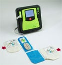
AED Unit. The automated external defibrillator (AED) unit pictured in Figure 7 illustrates how using a number of different molding techniques can achieve wide-ranging functionality for an assembly.
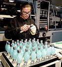
Overmolding was used on this unit for a variety of reasons. The most important requirements were shock absorption, impact resistance, and a watertight seal. The test protocol for the unit included passing a 1.5-m drop test, a cyclic loading test, and a water ingress test which submerges the unit in water. These requirements were possible to achieve only by combining a rigid, low-temperature, impact-resistant substrate material with a soft-touch overmolded TPU. The molded component resulted in an optimal performance-property profile for the AED unit. The top and bottom parts of the unit are designed as clamshells. The battery is included in the upper housing part. The upper and lower housing substrate parts are gas-assist injection molded and overmolded; the battery is overmolded twice. For the battery door, the first overmolding step adds the top soft-touch surface by insert molding. The second overmolding step molds a gasket onto the battery door to create a watertight seal.
Figure 8 shows a cross section cut through the top and bottom assembled parts of the clamshell of the AED, and clearly illustrates the overmolded gas-assist features of the medical device. The design requires high mechanical structural integrity and impact resistance, combined with a variety of other functional aspects. There are gas channels in both the upper and lower housings located on both corners of the cut. The cross section also illustrates the overmolded substrate structure for both housings and the double overmold for the battery door. Portable Defibrillator Unit. Another application showing the benefit of soft-touch molding is the handle shown in Figure 9 for carrying a portable defibrillator unit. Again, the requirements for the substrate material are impact resistance, structural integrity, and the ability to be overmolded. The handle part substrate is gas-assist injection molded in a first step and then inserted in a later step into another tool for overmolding with a TPU overmold. An added benefit of the gas-assist part is that it reduces the overall weight of the unit. The challenge in overmolding a gas-assist part lies in the proper selection of the gas-assist processing parameters. The cross section of the substrate handle part before overmolding is shown in Figure 10.
To survive drop and cyclic tests, the inside coring of the handle needs to be even throughout the part so that weak areas are not created. From a mechanical point of view, the hollowed-out cross section does not have much effect on the rigidity of the part. Indeed, the hollow section actually enables the part to survive high drops, thanks to its ability to distort under load. In general, when combining gas-assist and overmolding in a single application, it's important to ensure that the gas-assist part has enough remaining wall thickness for the overmolding process. Otherwise, the molding pressure to fill the tool with overmold resin might soften and distort the final part. Or, in a worst-case scenario, the pressure could even crush the substrate part.
Figure 9 also shows another approach to creating a soft-touch part using a rigid resin. In this case, the idea was basically to create rigid gas-assist structures (the blue handles on each side of the assembly) for impact resistance, with the added benefit of displaying a soft-touch perception. The material used for this application is a unique and proprietary blend of two different resins. The blend results in a material that produces a velvetlike surface along with other required functions such as shock absorption, noise and vibration dampening, and chemical resistance. Conclusion Overmolding, as an injection molding process, has evolved along with material advances over the past decade to produce new technical and creative opportunities for medical device applications. Beyond soft touch, the process offers numerous possibilities for designing parts with improved aesthetics, added functionality, brand identification, and increased value. Overmolding, a multimaterial process, enables device OEMs to take economical advantage of two or more materials with different properties by incorporating them into one molded component. Bibliography Defosse, M. “Design Focus: The Name of the Game Is Bond—Good Bond.” Modern Plastics [online] April 2005; available from Internet: www.modplas.com/search/search_article.php?searchfile=/2005/textfiles/feature/feature04012005_01.html&pub_date=1112313600. Ehritt, J. “Avoid Pitfalls in Multi-Material Molding.” Plastics Technology [online] June 2002; available from Internet: www.plasticstechnology.com/articles/200206ts1.html. Hansen, M.“Gas-Assist Injection Molding: An Innovative Medical Technology.” Medical Device & Diagnostic Industry 26, no. 8, 2005: 84–93. Hudacek, L. “How to Optimize Adhesion in Hard-Soft Overmolding.” Plastics Technology [online] February 2004; available from Internet: www.plasticstechnology.com/articles/ 200402fa2.html. Stewart, R. “New Polymers Offer Advantages for Medical Devices and Packaging.” Plastics Engineering 1, no. 10, 2005: 21–27. Michael Hansen is senior technical development engineer for Mack Molding Co. (Arlington, VT). He may be contacted at [email protected]. Copyright ©2006 Medical Device & Diagnostic Industry |
About the Author(s)
You May Also Like
