Sign up for the QMED & MD+DI Daily newsletter.
Hub Optimization and Integration of High-Performance Catheters
Originally Published MDDI January 2004Tubing Assembly
January 1, 2004
14 Min Read
.svg?width=850&auto=webp&quality=95&format=jpg&disable=upscale "Hub Optimization and Integration of High-Performance Catheters")
Tubing Assembly
Improving the design of a device such as a high-performance catheter must start with the components—from tubing to luers to final assembly.
Ron Roth and Alvin Coats
|
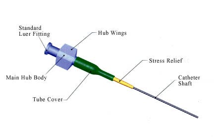
Figure 1. Critical elements of the typical hub-catheter assembly (Click to Enlarge). |
As minimally invasive medical procedures evolve, the design requirements for the medical devices used in them become increasingly complex. This is particularly true with high-performance catheter delivery systems. A successful catheter development project must be able to integrate, optimize, and thereby “fuse” the design and manufacturing requirements into a complete and cost-effective catheter system.
Of the various components in a finished catheter device, the hub (or handle) is typically one of the last items to be attached. It is often taken for granted in the design and fabrication process, and is given relatively little thought. However, given today's demanding device performance requirements, the hub and the hub-catheter interface can, in fact, make or break physician acceptance.
This article addresses the use of hubs in high-end, high-priced catheter systems. For these systems, the cost of the hub is a very small percentage of the total cost of the device. This overview is designed to help development and manufacturing engineers identify and focus on critical areas in the hub assembly process. Implementing these strategies should result in a better performing catheter with lower overall manufacturing costs.
Hub-Catheter
The critical elements of a typical hub-catheter assembly are the luer, the internal taper, the main hub body, the stress relief, the catheter shaft tubing, and, optionally, a stress relief cover (see Figure 1). The hub allows for access to the catheter lumen for a variety of functions, such as the injection of fluids or drugs, or the introduction of guidewires. For electromedical applications such as electrophysiology, the hub may also contain an electrical connector.
How critical these features are depends on the intended use of the catheter. When the catheter is used with a guidewire, for example, the smoothness and transition of the hub taper to the main shaft is more critical than when it is used for delivering drugs. And when drugs are delivered at high injection pressures, the pressure capability of the catheter, hub, and catheter-hub joint is more critical than it is for systems with guidewires.
A stress relief is integrated as part of the hub-catheter
interface. This component is typically 1–2 in. long. The stress relief allows for the mechanical forces involved in normal handling to be applied over a longer length of the catheter, so that the catheter tube does not prematurely kink.
It is also common for an outer tube (heat-shrink or snap-fit) to cover the hub-catheter assembly point. Besides masking the bond joint of the hub and catheter, which may not be visually pleasing, this outer tube can be labeled and color-coded.
Materials Choices
Key considerations in the selection of hub materials include biocompatibility, clarity, chemical resistance, rigidity, stability, manufacturing compatibility, and material costs. Functional requirements such as clarity involve the intended catheter performance as defined in the product specification. Likewise, meeting price objectives requires that design for manufacturability activities be included in the product development process.
Needless to say, the materials selected for the hub must meet the biocompatibility requirements established for the application. This is a complex topic that has been widely addressed elsewhere, and will not be discussed further here.
For low-volume, high-end catheter applications, the raw material costs are typically dwarfed by the costs associated with the project development and manufacturing processes. Therefore, raw material costs are not usually a major concern. For advanced catheter systems, engineering plastics such as nylon 12 are often chosen. Although the cost per pound for nylon 12 is higher than for other materials, it amounts to about 1% of the cost of the finished catheter.
In some cases, the finished device may require a hub made of clear material for functional or marketing reasons. If clarity is not required, the normal practice is to add a biocompatible colorant to the raw material, typically 1 to 2% by weight. The advantage of a colored hub is that the colorant hides cosmetic defects such as imbedded particles or bubbles, thereby resulting in a higher product yield.
For some fluid-delivery catheters, the ability of the catheter hub (and associated catheter tubing) to withstand chemicals is important. For example, some chemotherapeutic agents are known to attack and degrade certain polyurethanes.
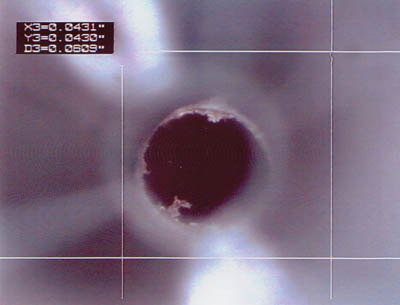
The hub material must be compatible with the manufacturing process chosen to assemble the hub to the catheter. For insert molding of the hub to the catheter, the hub material melting point should be less than that of the catheter shaft material. Otherwise, bubbles and excessive flash can result (see Figure 2). In general, like materials should be assembled to each other. For example, to optimize the strength of the bond, it is better to bond a nylon hub to a nylon catheter shaft than to a urethane shaft.
The catheter hub must have the rigidity necessary to handle all loads applied, including those imposed externally during normal handling and use by the physician. Likewise, the hub must be able to handle internal pressures (sometimes on the order of 300 to 1000 psig) that are applied during the injection of fluids.
The catheter hub must be stable during all manufacturing processes, including sterilization. Throughout the product's shelf life, the hub must maintain its specified physical parameters. And if clear, the hub must maintain its clarity for its shelf life. This objective can be ensured by working with material manufacturers, and demonstrated during accelerated life testing completed during product validation.
Standard Hub Specifications
As a starting point for any new design, engineers should refer to the ISO 594 standards for catheter and hub requirements.1,2 These standards are useful in defining the requirements for luer lock fittings in terms of dimensions, leakage, separation force, unscrewing torque, and ease of assembly when connecting a hub to a standard syringe.
For a high-performance catheter system, additional or more-rigorous requirements may be needed. For instance, ISO 594 requires a minimum hub pull strength to be determined by a functional test of the hub attachment to the catheter. For self-expanding-stent delivery systems, the hub pull strength is typically much higher than that specified by the ISO 594 standard. The actual requirement for these systems must be determined experimentally, through rigorous testing of the devices by simulated deployments of the stent.
Quality control inspections should ensure that key dimensional attributes, such as the hub inner diameter and other relevant features, are met. With both clear and colored hubs, an inspection for flash and internal bubbles or voids at the luer taper is required. The danger with internal flash is that small particles may break off when the catheter is used and can be introduced into a patient's vascular system.
Typical methods of detection involve viewing the luer port through a microscope. Internal hub voids can be found by using a standard probe that mimics the guidewire flexible tip. The standard should be used on all of the catheter-hub assemblies. The operator slowly passes the standard into the hub-catheter interface and attempts to detect interference or roughness. As with any attribute requirement, this test and the results obtained can vary from day to day and operator to operator.
To save time and money, equivalent hub-catheter functional units can be constructed for use as tensile test units. These functional units consist of the proximal catheter section, including the hub, strain relief, and 4–6 in. of the catheter tubing. In order for these test units to be effective, they must be generated in the same time period and under the same process parameters as the production units. It is also effective to use cosmetically flawed catheters as test units.
In the case of fluid-delivery systems, the hub-catheter system is commonly subjected to a leak-decay test or pressure test. In these tests, the distal tip of the catheter must be sealed temporarily to simulate a blocked catheter (a real-world, worst-case situation).
Manufacturing Methods
|
Figure 2. Plastic fragment observed in the hub luer (Click to Enlarge). |
A hub is usually attached to a catheter shaft by one of three methods: adhesive bonding, RF welding, or insert molding. Each of these methods has unique advantages and disadvantages when evaluated with respect to up-front development and manufacturing costs, yield, reliability, and resulting performance. For low-volume manufacturing, the adhesive bonding technique is likely to be used. In contrast, a high-volume/low-manufacturing-cost application would benefit from the use of insert molding.
Adhesive Bonding. This method requires the addition of a third material to the connection interface. For transparent hubs, UV adhesives are a good choice. For opaque hubs, choices range from quick-bonding adhesives such as cyanoacrylates to epoxy systems. Cyanoacrylates offer fast cure systems with no mixing or cure equipment required. By comparison, epoxy systems typically offer better bond strengths and long pot lives. The disadvantages are that most epoxies are two-part systems that must be mixed and cure time is typically 24 hours. Although cure time can be shortened to 1 hour by oven cure, this expedient requires additional equipment and staging space.
Adhesive bonding of catheter hubs has some significant advantages over other hub attachment methods. It is less important to match the hub and catheter-shaft materials. Adhesive bonding thus more readily allows the use of off-the-shelf hubs. If a custom hub is required, it can be developed rapidly and at a fairly low cost. A disadvantage of this method is that the results may be less repeatable compared with other manufacturing methods, as it is dependent on the operator. Also, if epoxies are used, significant staging space may be required to allow the adhesive to cure. Finally, some adhesives involve the use of solvents that may require venting.
RF Welding. RF welding can be an effective method for attaching a hub to a catheter shaft. In RF welding, the interface between two parts is heated close to the materials melting point. In the ideal situation, the two different parts become one at the interface, and the bond is as strong as the hub and catheter-shaft materials.
The advantages of RF welding are a short manufacturing cycle time, the ability to weld multiple parts at one time, repeatable results, and small set-up space. The disadvantages are the capital expenditure required to purchase the equipment, the longer development cycle required to design tooling and die, and the time required to determine the proper processing parameters. In addition, not all catheter and hub materials may be RF welded. RF welding is most useful for joining plastics that have strong dipoles such as PVCs, polyurethanes, and nylons.
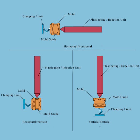
Insert Molding. Much like RF welding, insert molding results in the interface between the two parts melting and flowing together. Insert molding of the hub onto the catheter shaft is completed in a customized injection molding machine. The hub injection molding equipment must be compatible with the insert molding manufacturing method. Three unique orientations are possible for the injection machine's clamp/screw: horizontal-horizontal, horizontal-vertical, and vertical-vertical, as illustrated in Figure 3. Of these three, a vertical-vertical configuration is preferred. This configuration provides space outside the active molding space for the catheter shaft itself, so that it is not damaged during the molding process. Because the catheter shaft is present during the molding process, cleanliness in the manufacturing environment is critical.
|
Figure 3. Possible orientations for the injection machine's clamp/screw (Click to Enlarge). |
The advantages of the insert molding process are a short manufacturing cycle time, the ability to process multiple parts at one time, and repeatable results. The disadvantages of this process are the high capital expenditure and the long manufacturing development cycle. As with RF welding, not all catheter and hub materials may be successfully joined together by insert molding. For example, it is difficult to insert mold a high-temperature material such as nylon 12 onto a lower-melting-temperature material such as Tecoflex 80A.
Bond Strength
For catheter systems with a high manufacturing cost, the ability to rework a hub-catheter assembly should be developed as part of the overall manufacturing strategy. The rework option requires that the final catheter have sufficient length tolerance to allow for cutting off and rejoining the hub multiple times.
To maximize bond strength and reduce the amount of rework required, the following guidelines are helpful:
•Maximize surface area. In general, as the total bonding surface area increases, the overall strength of the assembly also increases.
•Verify material compatibility. As discussed above, ensuring the compatibility of the hub and shaft materials is essential.
•Roughen the surface. The outside surface of the catheter shaft can be roughened in order to effectively increase the bonding area to which the hub is connected.
•Follow best practices. The assembler should wear gloves to prevent coating of the parts with oil and sweat.
•Clean parts carefully. The catheter shaft should be cleaned to remove oil and other residual materials with solvents such as IPA and MEK, depending on the catheter materials. The bonding surfaces may also be treated with plasma systems.
These practices provide the smallest variation in the resulting bond strength of the hub-catheter system. They are typically built into the design itself (e.g., the surface area) as well as into the catheter manufacturing work instructions.
Hub Design and Manufacturing Optimization
Many commercially available mold design software packages can help avoid hub manufacturing issues. These software tools allow for analysis of the hub design and mold before it is constructed, leading to a shortened development cycle. The ideal situation is for the raw material to reach all points in the hub mold at the same time and under the same stress. The outputs of these software systems can help determine the number and location of the mold gates and ensure that the raw material is not overly stressed at any point along the injection path.
As with any injection-molded part, a number of things can go wrong with a hub during molding. These failure modes include bubbles, excessive flash, cosmetic issues, stress cracking, incomplete filling, and dimensional problems caused by excessive material shrinkage. Some common problems have nothing to do with the hub design or the hub mold, but with the equipment or setup. For instance, external flash may be encountered when the tonnage of the machine is not high enough or the hub mold is misaligned. While there is no penalty for using equipment with excessive machine tonnage, the resulting part price may be higher than if a smaller machine were used.
Black particles may be encountered when the equipment is not cleaned at the required frequency. This failure mode may also occur when the plastic material remains within the barrel too long before being fed to the mold. Of course, such particles may also originate in the raw material as supplied.
Incomplete filling may be caused by incorrect process parameters. As a starting point, the raw material suppliers will typically recommend the initial process parameters to be used. This failure mode may also be caused by incorrect gate sizes, gate locations, runner sizes, runner lengths, and an incorrect shot-size to shot-capacity ratio.
A discolored hub indicates that the raw material has been overstressed during molding. Cases where the entire hub is discolored or opaque indicate a problem with the gate locations and size. Likewise, localized discoloration of the hub indicates that the raw material has been overstressed locally and that the hub design itself, as well as the gate locations, need to be examined.
Completing software analysis before investing in a mold will prevent project cost overruns by avoiding issues later on in the development schedule. This software assessment should be balanced with previous case histories from other catheter projects, if available. Likewise, inputs from injection molding experts, as well as equipment suppliers, are useful during the development and implementation stages.
Conclusion
Given the competitive forces in today's medical device market, completion of the product development cycle on time and on budget is a must. As part of the development process, the right decisions must be made with respect to hub and catheter shaft materials, hub geometry, and manufacturing methods. The decision-making process can be assisted by the development team's work experience, reviewing best practices demonstrated by current catheter systems on the market, and commercially available software tools. It is important that engineers address the critical elements of the product. The guidelines discussed in this article will allow the designer and manufacturing engineer to meet or beat the expected the product development cycle while ensuring a robust product design.
References
1.ISO 594-1:1986, “Conical fittings with a 6% (luer) taper for syringes, needles and certain other medical equipment—Part 1: General requirements” (Geneva: International Organization for Standardization (ISO), 1986).
2.ISO 594-2:1998, “Conical fittings with 6% (luer) taper for syringes, needles and certain other medical equipment—Part 2: Lock fittings” (Geneva: ISO, 1998).
Copyright ©2004 Medical Device & Diagnostic Industry
You May Also Like

.png?width=300&auto=webp&quality=80&disable=upscale)