Covering the Spectrum
May 1, 1999
Medical Device & Diagnostic Industry Magazine
MDDI Article Index
An MD&DI May 1999 Column
Lasers meet wide-ranging requirements for welding and drilling applications in medical manufacturing.
Laser technology has matured to meet a wide range of manufacturing needs, from low-power, low-pulse-rate Nd:YAG (neodymium:yttrium/ aluminum/garnet) to kilowatt-level continuous-wave (CW) CO2 systems. Lasers are used in all aspects of electronic assembly and in fabrication processes involving materials that are less than 1 mm thick. They are also the tools of choice for many materials-joining applications, such as medical device manufacturing and assembly, that require controlled heat input, a small heat-affected zone, precision automated control, and high-volume, high-yield production.
Because lasers are so widely used and so useful, knowing about the latest developments in these tools is a must for medical manufacturers. A review of the types of lasers, some medical manufacturing applications for lasers, and some of the most important considerations for laser use will provide manufacturers with a basic understanding of these devices.
LASER TYPES
Lasers are made from a variety of materials that yield various output radiation wavelengths, ranging from argon/fluorine gas in the deep-ultraviolet range at 193 nm, to CO2 at 10.6 µm, and methyl-fluoride at 500 µm. Commercially available systems are typically solid-state Nd:YAG at 1.06 µm or CO2 gas at 10.6 µm. Solid-state diode lasers in the 850–980-µm range are now available with useful output powers and reliable performance. Excimer lasers in the 250–350-nm range are finding increased use in the preparation of plastic surfaces and ablation of epoxy residues after rework operations.
Despite obvious differences in output lengths, all laser types are based on the same principle of operation, which gives them their name: light amplification by stimulated emission of radiation.
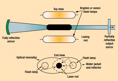
For Nd:YAG systems (Figure 1), for example, the doped YAG crystal is stimulated by one or two high-energy flash lamps. The stimulation causes neodymium atoms in the rod to produce light. This output light lasts for essentially the same duration as the flash lamp pulse.

Figure 1. A typical Nd:YAG laser system.
Solid-state control of the flash lamp power supply, pulse rate, and pulse width allows very precise laser output. Higher power can be achieved by increasing the collision frequency between the flash lamp photons and the laser rod. This increase is typically accomplished by placing a fully reflecting mirror at the rear of the laser head and a partially reflecting mirror at the output end. With the mirrors, some of the laser output is reflected back down the axis of the rod, causing further stimulation of the crystal.
A major advantage of Nd:YAG lasers is that fiber-optic cables can efficiently carry the output frequency of 1.06 µm. This ease of fiber-optic transmission has enabled the development of production systems based on multiple output cables connected to a single laser source. The flexibility of the fiber-optic cables can also allow the focus optics to be placed on the articulated arms of robots, allowing versatile, multiaxis laser processing. Fiber-optic beam delivery can be achieved at distances in excess of 30 m.
Like Nd:YAG systems, diode lasers are solid state and achieve emission of radiation by electrical stimulation of specific regions in the semiconductor crystal. Diode lasers typically use layered combinations of gallium arsenide and gallium aluminum arsenide as the lazing structure.
Similarly, the CO2 laser (Figure 2) achieves its output beam by electrical stimulation of CO2 gas. The gas is contained under low pressure in a glass tube with front and rear mirrors positioned in the same configuration used in a Nd:YAG system.

Figure 2. A typical CO2 laser system.
Stimulation of the gas by direct current or radio-frequency energy can be achieved in either pulsed or continuous modes. The stimulation causes photon generation in the gas and production of a usable output beam. Like that of the Nd:YAG, the CO2 laser's output beam replicates the stimulation pulse in duration. CW CO2 systems are common and can reach higher power levels (>20 kW) than most solid-state systems. The CO2 output frequency of 10.6 µm is not compatible with fiber-optic cabling, so this laser type requires solid optical tubes with glasslike lenses to transmit its beam.
Other laser types, such as the excimer laser, also use reactive gases and are configured like the CO2 laser.
MEDICAL APPLICATIONS AND LASER PARAMETERS
With the range of laser types available, manufacturers can use lasers for many widely differing and difficult applications and for processing a variety of materials (Table I).
Material | Weldability | Laser System |
|---|---|---|
Gold | Excellent | Nd:YAG |
Platinum | Excellent | Nd:YAG |
Tungsten | Good | Nd:YAG |
Titanium | Poor–good | CO2/YAG |
Stainless steels | Excellent | CO2/YAG |
Nickel alloys | Good–excellent | CO2/YAG |
Alumina | Poor | CO2/YAG |
Glasses | Poor | CO2 |
Polyethylene | Good | CO2 |
Polypropylene | Good | CO2 |
Table I. Many of the materials listed above are used in the manufacture of medical devices, such as sensing electrodes, neurosurgical clips, orthopedic prostheses, electronic packages, endoscopic tools, catheters, lumens, and packaging.
Drilling. One of the key process capabilities of lasers is drilling. A wide range of materials, including plastics, paper, ceramics, and metals can be laser drilled.
In this application, a laser is focused to a fine spot at or just below the material surface. A small cone is attached to the lower portion of the focus head and an assist gas is pumped through, which results in a coaxial gas flow with the laser beam. This assist gas can be oxygen, helium, argon, or nitrogen, or mixtures of these gases. The purpose of the assist gas is to help eject the molten material from the hole and also prevent it from spattering on the focus lens.
Laser-drilled holes are often high in quality, with little kerf, breakout, or recast, although deep holes can result in some taper. The key advantage to laser drilling is that it produces no tool wear and, if CAD driven, is extremely fast and flexible.
Processing Plastics. Many plastics, which are used in the manufacture of instruments, catheters, insulation, tubing, syringes, and packaging materials, absorb infrared energy at the CO2 wavelength of 10.6 µm. The shorter-wavelength Nd:YAG is often transmitted through plastics with little interaction. Filled resins, however, are often strong absorbers at the Nd:YAG wavelength.
Thin sheet stock (0.1 and 0.2 mm) of polyethylene and polypropylene has been welded using powers of 100 W at rates up to 50 m/min. For welds made using the CO2 laser, parent-material strength can be achieved. For Nd:YAG welds, however, the joint fails in tension at between 70 and 80% of the parent-material strength.
Sealing Pacemaker Housings. Implantable pacemakers require hermetic sealing of two clamshells, typically fabricated of titanium or corrosion-resistant nickel-alloy steel. A key requirement for this type of assembly is low heat input so that internal electronics will not be damaged.
Lasers have been used to fusion weld covers to housings within 0.030 in. of heat-sensitive devices. The steel materials can be welded with either pulsed YAG or CW CO2. Cover gas, such as argon, nitrogen, or a mix of argon/helium, is recommended to reduce discoloration of the surface. The inclusion of helium in the cover-gas mix can also serve as the tracer gas for subsequent leak testing.
Titanium alloys are not difficult to weld. CO2 systems are used with careful control of cleanliness and cover gas. Exclusion of oxygen is important for titanium welds to avoid embrittlement. Weld penetration and speed are similar to those used for stainless steels. A general rule for power requirements is 1000 W per 1.0-mm thickness. This ratio can be scaled for thinner or thicker steel or titanium as required. Using this ratio, 0.2-mm stock could be welded using approximately 200-W average power.
Assembling Endoscopy or Arthroscopy Instruments. Many surgical instruments are fabricated using stainless-steel alloys. Often the requirements include the joining of dissimilar alloys, such as hard 440 alloy to 316L stainless. With careful control of weld penetration and heat input, these can be welded without cracks by Nd:YAG or CO2 systems (Figure 3).
 Figure 3. A cross section of 300-series stainless steel welded to 440 alloy. This combination is generally considered unweldable, but as the micrograph shows, the weld zone is crack free. This weld was produced using a rapid pulse and small weld zone, which provided little time for cracks to form.
Assembling Implantable Devices. Lasers can be used for precision spot welding as well as continuous seams. Spot welds can be made using pulsed CO2 or pulsed YAG join wires used for electrodes or implantable sensing devices. In these applications, the laser is used to fuse the ends of wires together.
An advantage of spot welding is that insulated materials can be joined. The laser pulse can be set to ablate the coating and then have sufficient energy to fuse the wire ends. A drawback of this technique is that postweld operations are required to remove weld flash or resize the fusion nugget. As the wires melt together, a circular ball is formed that is typically larger in diameter than the parent wires. Wire joining can also be very difficult to fixture properly. Missed welds result in the melting back of each wire into individual balls.
Lasers can also be used to prepare surfaces for bonding or to clad thin layers to the surface. This could be useful in the preparation of joint replacements, to improve the bonding between the implant and patient bone. Corrosion of some alloys is improved by cladding the surface with nickel-rich or ceramic-bearing alloys. This cladding is achieved by introducing a stream of powdered alloy to the surface of the part, coincident with the laser beam. The powder alloy and the beam interact, and the alloy is fused to the surface. Continuous films of materials can be grown using this method.
Other implantable devices are fabricated using glasses, most often borosilicate. Just recently, researchers have developed weld profiles to join glass components. The welding of glass is not difficult to achieve using the CO2 laser, but temperature control is critical to avoid cracking. Most studies have concluded that preheating to 800–1100°C is required, with the postweld cool-down rate carefully controlled. The ability to join glass components allows manufacturers to fabricate medical devices with improved corrosion resistance, because of the elimination of exposed metallic layers.
LASER PROCESSING ISSUES
When using lasers, a variety of parameters must be controlled to ensure that the part will not be damaged and that the processing is successful.
Key processing parameters for pulsed systems are pulse energy, pulse width, pulse repetition rate, and the feed rate of the motion system (Table II). Other key elements are the focal length of the focusing optics, the focal height for the parts to be welded, and beam alignment to the joint. In CW mode, power and feed rate are also important considerations.
Property | Factors | Effect |
|---|---|---|
Power density | Peak power/spot area | High = weld spatterLow = no coupling |
Mean power | Peak power x pulse duration x pulse frequency | Determines speed for given thickness |
Pulse energy | Peak power x pulse duration | Penetration |
Pulse frequency | 1/pulse duration | Bead continuity |
Duty cycle | Pulse duration/pulse period | Performance (penetration, speed) |
Applied energy | Applied power/welding speed | Maximum penetration at high speed |
Shielding gas | Flow rate | High = cutting and porosity |
Table II. The key parameters that can affect laser welding.
Laser energy interacts with a material to form a fusion zone (Figure 4). In most applications, the laser energy is used to melt the parent material, which is ejected from the weld area in cutting and drilling, or reflowed to form a nugget in welding.
 Figure 4. Laser energy interacts with materials to form a fusion zone.
 Figure 5. An example of a solid-state weld formed by a resistance process.
 Figure 6. An example of a fusion weld formed by a resistance process.
Most laser interactions in microjoining involve fusion of the parent materials, although there are other applications, such as surface cladding.
Laser joining is very different than resistance welding, another often-used joining technology. In resistance welding, the heat input is altered to provide solid-state or fusion-type welds (Figures 5 and 6). Solid-state welds are joints that do not require melting and recrystallization of the parent materials. Resistance welds can be thought of as forming from the inside out, as a result of the contact resistance at the joint interface. Because the heat is generated at the interface, the weld nugget forms first at the internal interface and grows outward and, in fact, can be completed with little damage to the surface of the part.
Laser welding, in contrast, introduces energy into the interface. It will always alter the part surface and typically result in parent-material fusion.
A significant concern in laser welding is proper fixturing of the joint. This is especially important in microjoining applications, in which accidental cutting of the top material is often easy to do.
Typically, laser microwelding can be achieved at gaps no larger than a few thousandths of an inch, with a maximum gap of 10% of the material thickness. Obviously, with these tight tolerances, intimate contact of the materials is the preferred fixturing condition.
Laser weld zones also shrink, with the top of the weld bead left in tension. Care must be taken in welding thin-walled boxes or other enclosures to ensure that warp and twist of the joined parts will not be an issue.
Too much restraint can also be a problem, in that the weld pool can be made to crack. The weld pool must be able to take the strain of cooling and shrinking, and rigid fixturing can add to the stress on the pool.
Finally, the degree of heat sinking caused by the fixtures can affect the final performance of the weld. The weld zone microstructure is a direct function of the cooling rate of the weld pool.
For most thin materials used in microjoining, heat dissipation in the parts is very rapid and largely a function of the pulse energy and pulse width. For critical electronic applications, copper fixtures are often used to clamp the parts as close to the weld zone as possible to minimize heat input to the bulk of the assembly.
In addition, high peak powers can be used with short pulse widths. This has the effect of minimizing the overall average power and, therefore, the heat generation in the device.
THE EFFECT OF WAVELENGTH
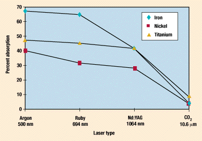
The ability to form a fusion joint using lasers is dependent on coupling the laser beam with the material. Energy transfer to the part is a function of the laser frequency and the material type (Figure 7).

Figure 7. The laser absorbance of several materials.
Materials that have a high thermal conductivity, such as copper, silver, and aluminum, will generally require short-wavelength light, such as Nd:YAG, for processing. Those with poor thermal conductivity, such as steel, can be welded and cut with CO2 systems.
This is not a rigid rule, however. Thin sheet stock of stainless steel can be successfully welded with a Nd:YAG laser that has a very precise penetration depth. Further, a material such as gold, which has a smooth, highly reflective surface, may require a higher initiation pulse to begin the fusion process. Subsequent pulses can then be of lower energy.
Spot welding and seam welding are possible with most systems, whether pulsed or CW. Pulsed welds are typically achieved by matching the laser pulse rate and table feed rate to yield a pulse-to-pulse overlap of 75%. For CW systems, once melting is initiated, the fusion zone is pushed along the path of the laser.
CHOOSING A LASER SYSTEM
Manufacturers should purchase a laser system that will produce two times the power needed for the required application. Laser systems that produce average output power of less than 500 W are considered low-power systems. Many microjoining applications are achieved at laser powers less than 100 W.
Most laser systems contain:
A laser head, which generates the beam.
An optics assembly, which transports the beam to the workpiece.
A power supply to generate and direct the current to the flash lamps.
A closed-loop water chiller to cool the laser head.
A motion control system to move the laser focus tube or an x-y table.
Beyond these general rules, there is a vast array of possibilities for medical manufacturers. Lasers can be used in medical applications ranging from processing plastics to sealing pacemaker housings, and, as laser technology continues to improve, the list of applications continues to grow.
BIBLIOGRAPHY
Dawes, C. Laser Welding. Princeton, NJ: McGraw-Hill, 1992.
Fleming, DG and BN Feinberg. Handbook of Engineering in Medicine and Biology. Boca Raton, FL: CRC Press, 1976.
Jones, IA and NS Taylor. "High Speed Welding of Plastics Using Lasers," in Proceedings of the Antec Conference. San Francisco, May 1994, 1360–1363.
O'Brien, RL. Welding Handbook. 8th ed. vol. 2. Miami: American Welding Society, 1991.
Sun, Z and JC Ion. "Laser Welding Dissimilar Metal Combinations." Journal of Materials Sciences 30 (1995) 4205–4214.
Kevin J. Ely, PhD, is team leader, microjoining and plastics, at Edison Welding Institute (Columbus,OH).
Copyright ©1999 Medical Device & Diagnostic Industry
You May Also Like


