
Sign up for the QMED & MD+DI Daily newsletter.
Using CAD/CAM to Communicate Design Intent
Contract manufacturers and their medical device OEM partners often struggle to communicate design intent. Eliminating miscommunication helps avoid project delays, confusion, and added costs.
Greg Berrevoets
March 1, 2013
7 Min Read
.svg?width=850&auto=webp&quality=95&format=jpg&disable=upscale "Using CAD/CAM to Communicate Design Intent")
Some methods that can improve the process include examining prints and removing information that distracts from the engineers’ design intent. An innovative approach to design intent looks at geometric design and tolerancing (GD&T) not only as a communication tool, but also as a business strategy. This article explores how a manufacturer can use a GD&T strategy to clarify design intent, streamline the manufacturing and inspection process, shorten time to market, and reduce costs.
Prior to the broad application of computer-aided design (CAD) and computer-aided manufacture (CAM) software in the late 1980s design engineers would sit at a drafting table and laboriously dimension prints with tolerancing. Changes were made with a mechanical pencil and a pile of eraser crumbs. That all changed with the mainstreaming of CAD software and solid modeling.
Today, if it were possible to create the perfect mathematical part, it would look exactly like the solid model. To get that perfection, firms must first examine ASME Y14.5 "Dimensioning and Tolerancing" and Y14.41 "Digital Product Definition Data Practices Standards." These documents provide the common language of GD&T and methods to communicate it.
Historically, many engineers would go by the saying that “more is better” when dimensioning a drawing. If one callout for parallelism wasn’t sufficient, then three or four were better. This thinking led to drawings cluttered with multiple data and tolerance schemes. As parts got smaller and more complex, the confusion grew worse. And the true meaning of the drawing—the design intent—was lost in a mish-mash of overly complicated tolerancing schemes. It created problems throughout the entire product development process. Those schemes needed to be designed, manufactured, and inspected, but the lack of clarity caused repeated problems and delays at each step.
|
Figure 1. This 2-D orthographic drawing has too many inspection points. |
Figure 1 shows a tolerancing scheme run amok. A theoretical ring has complex features, in this case a series of small arc radii.
If you were to inspect each of these dimensions, you’d be looking at hundreds of features that are called out, including 74 angles, 222 radii, 74 peak-to-peak amplitudes, 74 angles, 74 points on the minor radius, and 74 arcs of the outside radius. Anyone who has attempted to measure a small radius with any certainty based on three measured points knows the li3kelihood of introducing error—in excess of 100%. Overdimensioning creates confusion and opportunity for error. These errors are then repeated at every stage of development. The problem is compounded when a contract manufacturer is brought into the picture. A lot of inside knowledge is required to fudge this part through the inspection process. When a contract manufacturer is involved, unless that inside knowledge is passed down, design intent is lost. The precise language of GD&T, in conjunction with the 3-D solid model, can help.
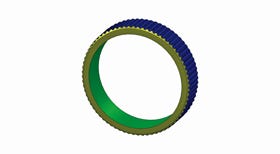
Using precision GD&T to not only dimension the part, but to describe its functionality is a different approach. It starts with the solid model. CAD/CAM software enables part design that is mathematically perfect and depicts it in the 3-D solid
model. Perfect models always represent the mid geometry of the defined tolerance zone. The example in Figure 2 is the 3-D solid model for the same theoretical ring shown in Figure 1. This model contains nominal geometry of the mathematical perfect part. Querying digital elements provides the dimensions, relationships, and attributes necessary to manufacture the part. The model is only one component of the product definition data set used in parallel with the drawing graphic sheet and external documentation.
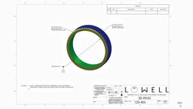
The next step is to take the 3-D solid model and use it as the baseline for creating the drawing. The key is that the print reflects the model in describing the conformance criteria of the part—not just dimensioning features. Start by only including information that relays the engineers’ design intent. In the drawing, only GD&T reference frames, data, and engineering specifications are shown. In Figure 3 it is clearly conveyed that the central holes’ axis, not the outer diameter axis, determines how the outer profile is defined, measured, and analyzed. When executed correctly, this results in a reduced-content drawing with less clutter than the traditional drawing and more usable information.
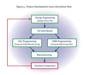
The 3-D solid model used in tandem with 3-D-model-based drawings eliminates questions. Figure 4 (p. S-54) depicts an effective product development processs that eliminates design ambiguity. Once the design is settled, a contract manufacturer can use the design model to build the manufacturing and inspection programs. On the CAM side, the model is the basis for the machining programs. The same model is used to program a contract manufacturer's coordinate measuring machine inspection protocols. Inspection data are then analyzed and catalogued, usually with proprietary software. These inspection data are critical for set up, in-process, and final inspection. With this approach, only one 3-D solid model is used to generate design, manufacturing, and inspection data. All the information is stored within the design history file for a clean record of all life cycle activity. The benefits of speaking in the common language of GD&T at each step of the process include clear depiction of design intent and, therefore, fewer project delays.
|
Figure 4. Use a product development cycle information flow. |
Tips to Ensure a Partner Can Communicate Design Intent
A commitment to communicating design intent is a true indication of partnership between a medical device manufacturer and its supplier. Some questions to ask to ensure your suppliers clearly understand your design intent are as follows:
?Do they have advanced training in GD&T from an organization such as the International Institute of Geometric Dimensioning and Tolerancing? Do any of their engineers have certifications from ASME?
?Do they routinely use the solid model as the basis for understanding of design intent? Can they point out areas where that intent is unclear?
?How comfortable are they with 3-D model drawings and the use of profile tolerancing?
?Have they invested in the high-end physical metrology equipment, such as a Leitz precision measuring machine, needed to measure complex geometries with small deviations?
?Have they acquired profile analysis software, such as SmartProfile, needed to analyze complex surface profiles?
Only by partnering with a supplier that understands, invests in, and is committed to clear communication of design intent through GD&T can designers and suppliers speaking in a common language that communicates design intent free of ambiguity.
Conclusion
The long-term gains for adopting GD&T and 3-D model drawings are many. One of the clearest is that the true design intent is conferred, and it survives changes in personnel, manufacturing, and inspection equipment. Inside knowledge is replaced by the language of GD&T, which promotes continuous product improvements, line extensions, and accessory development. In addition, there is absolute clarity when working with contract manufacturers that may not have been along from the beginning of the development cycle. The solid model, when used in conjunction with 3-D-model-based drawings and GD&T, can clarify design intent, shorten lead times, reduce errors, and ultimately reduce costs.
Acknowledgement
The author wishes to thank Greg Hetland of the International Institute of Geometric Dimensioning and Tolerancing for editing and assistance with the figures and models for this article.
 Greg Berrevoets is a new product development engineer for Lowell Inc. (Minneapolis, MN). He has more than 20 years of experience in the medical device industry. Berrevoets is a certified GD&T Professional through ASME and Six Sigma Black Belt. Contact him at [email protected]
About the Author(s)
You May Also Like

.svg?width=300&auto=webp&quality=80&disable=upscale)