New Extrusion Techniques Advance Catheter Design
Innovative processing technologies can help designers create products that perform better and cost less.
February 21, 2013
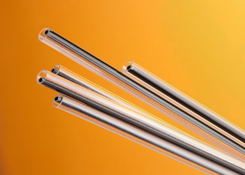
Medical tubing used in minimally invasive devices has become increasingly sophisticated. Today’s cutting-edge devices are reaching more remote regions of the human anatomy and are used to perform greater diagnostic and interventional procedures, requiring different performance properties on the exterior and interior of the catheter shaft and along the length.
The performance characteristics necessary for catheters to reach smaller distal areas within the body include pushability, torque transmission, and flexibility. Catheters are inserted into a vascular passage from a peripheral location, such as the femoral artery. The physician advances the catheter by pushing it from the proximal end and provides direction with rotational inputs that are transmitted by way of torque from the proximal end to the advancing distal tip. At the same time, the catheter must remain flexible to navigate the complex turns and branches inherent in the vascular system. For shafts made from single materials and continuous cross-sectional configurations, these characteristics are contradictory. The material and design properties that increase pushability (without kinking) and torque transmission reduce flexibility, resulting in a shaft that is less capable of navigating tortuous anatomies.
Three primary variables affect the performance characteristics of a device: materials, design, and process. Catheters use a limited number of commercially available polymers suitable for in vivo application and with desired characteristics. Most polymer manufacturers offer multiple grades that provide a range of properties suitable for most applications.
Catheter shaft dimensions are typically constrained. Outside dimensions are constrained by the size and configuration of the vascular passageway through which it is inserted. Inside dimensions are often constrained by the necessary working channels through which fluids, gases, or devices must pass for diagnosis or therapeutic intervention.
Catheter designers increasingly rely on processing technologies—particularly extrusion—to create shafts using variable materials and configurations in continuous processes for greater product performance and reduced costs for advanced catheters.
Common Materials
Thermoplastic polyurethanes are one of the key polymers in the vascular catheter market. The diversity of urethanes used in catheters is significant. Polyurethanes varieties include polyester, polyether, and polycarbonate-based varieties, as well as aromatic and aliphatic grades.
Polycarbonate-based polyurethanes exhibit excellent long-term biostability and are commonly used in applications that are in the body for long periods. Aliphatic and aromatic polyether-based polyurethanes soften at body temperature, which promotes patient comfort and reduces the risk of vascular trauma. These are commonly used for in-dwelling catheters, such as a peripherally inserted central catheters (PICC) and central venous (CV) catheters.
Polyamides (nylon) and polyamide block copolymers (PEBA) are materials of choice in applications such as percutaneous transluminal coronary angiography (PTCA) applications, including balloon and stent delivery devices, where greater stiffness is required and softening at body temperature is not desired.
PEBA are modified nylons with soft segments that provide more elasticity than polyamide 11 or 12. They have become materials of choice in many interventional catheters because they combine the flexibility and softness of polyurethanes with the strength of nylons.
Polytetrafluoroethylene (PTFE) is the most ubiquitous fluoropolymer for vascular catheters. It is most commonly used as a lubricious inner catheter liner because it has the lowest coefficient of friction of all catheter materials. Catheters using PTFE are usually hand-assembled because PTFE cannot be melt-processed by conventional extrusion methods.
Coefficient of friction is the ratio of the force of friction between two bodies and the force pressing them together. The coefficient of friction depends on the materials used.
High density polyethylene (HDPE) can also be used as a liner for the inner lumen of vascular catheter designs and as a complete shaft because it can be melt-processed by extrusion. It does not have as low a coefficient of friction as PTFE but is superior to polyamides and polyurethanes. It is also harder than PTFE, which can result in a lower effective coefficient of friction compared with PTFE in some applications. Where devices or components are advancing down a working channel, PTFE has a tendency to plow up in front of the component, increasing the deployment force. Because HDPE is harder, it does not plow up, reducing the deployment force even though the coefficient of friction is higher.
Polyvinylchloride (PVC) was one of the first materials used for vascular catheters but has since been replaced in many catheter designs by polyurethanes and polyamides.
Thermoset polyimides are manufactured in a solvent-based layering process and heat cured. The process can create very high-strength, thin-wall tubing in a range of diameters. Polyimide (PI) tubing is often used to access small vessels in the neck, head, and brain or as precision liners for lumens.
Polyetheretherketone (PEEK) is increasingly being used in catheters where high strength or heat resistance is required, such as ablation devices. PEEK has similar mechanical properties to polyimide, but it is a true thermoplastic and can be extruded in a continuous process.
Longitudinal wires or fibers may also be incorporated into extrusions to provide structural support. These include coil configurations to resist crush and buckling, and braid configurations to improve burst strength and torque transmission. Reinforcement materials include stainless steel, nitinol (nickel titanium), or high-tensile polymer fibers.
Lumen Designs
Catheters consist of long, thin tubes, often with access structures on the proximal end and working openings on the distal end. Catheter shaft designs are commonly developed around the required lumens along the length of the shaft. In medical catheter design, the term lumen refers to the passageways through the length of a catheter. Lumens are used to transport liquids, gases, or surgical devices during a medical procedure. There can be a single-lumen device or multiple lumens, and the configurations and numbers are almost limitless.
Single lumens are most commonly used in IV, urological, and drainage catheters. Two- and three-lumen configurations are often used in peripherally inserted PICC lines.
PTCA catheters with two-lumen configurations will have a smaller round lumen for guide wires, leaving a large crescent lumen for balloon inflation. Feeding tubes and atomizing drug devices often require a series of lumens around the perimeter of the extrusion.
Lumens do not have to be round, and they do not have to be of the same configuration. A common configuration used in thermodilution catheters used to measure the output of the heart has triangular lumens resembling a pie.
Design for Insertion and Navigation
First and foremost, a catheter must be capable of reaching its designated anatomical site to perform its diagnostic or therapeutic objective. For urinary catheters (also called Foley catheters) or peripherally inserted PICC lines, the pathway and distance the catheter must traverse is relatively uncomplicated. In such cases, a single material of construction, single- or multiple-lumen configuration, and consistent cross-sectional dimensions along the length of the catheter shaft are suitable.
|
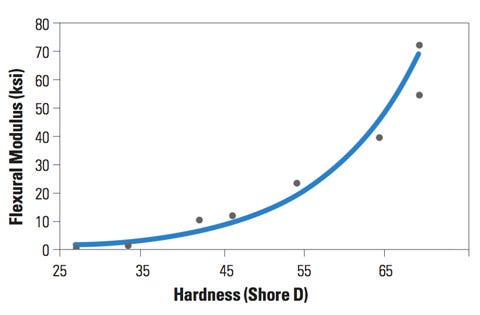
Figure 1. This graph shows the relationship between PEBA stiffness and hardness. |
Catheters that must travel longer distances in the body through complex vascular channels provide a greater design challenge. To reach these distal regions, often from a peripheral access point such as the femoral artery, catheters are pushed and twisted until the tip reaches its destination. While physicians often evaluate such devices by how it feels during the procedure, design engineers can use basic structural equations to guide material selection and design configurations.
For years, the term durometer has been used as a surrogate for a basket of catheter material properties. Durometer is a measure of a material’s hardness and can be used to predict the performance of a catheter shaft. For example, a catheter shaft tip must be soft enough that it does not cause damage as it progresses through vascular pathways. However, durometer is an indirect measure of catheter flexibility. Hardness is even less directly correlated to catheter pushability or torque transmission.
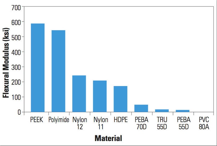
Tube rigidity, column buckling, and torsion equations can be used to mathematically predict catheter bending, pushing, and twisting performance of a catheter, respectively. In these equations the elastic modulus of the material is used to predict product performance (see Figure 1). That said, there is empirical evidence of a correlation between hardness and modulus. In general, the higher the hardness value, the stiffer the material. This suggests that material durometer is a reasonable second-degree surrogate predictor of performance (see Figure 2).
Cross-sectional dimensions also have a profound effect on shaft stiffness, pushability without kinking (i.e., buckling), and torque. Column buckling, tube rigidity, and torque transmission are directly proportional to the cross-sectional catheter design, represented by the cross-sectional moment of inertia.
|
Figure 2. This graph shoes the flexural modulus of common catheter materials. |
The juxtaposition of these formulas highlights an increasing challenge for design engineers. The same material and dimensional properties that increase pushability (resistance to compressive load without kinking) and torque transmission (from the physician’s hand at the proximal to the distal tip) also increase rigidity and make the shaft less flexible for vascular passage.
To navigate this challenge, design engineers use more than one material of construction (each with a different modulus) along the length of the shaft. Additionally, cross sections may be tapered at the distal end to reduce the moment of inertia and improve flexibility.
Previously, a catheter with multiple materials along the length of a shaft was manufactured by extruding discrete segments and bonding or fusing them manually. Today, intermittent extrusion technology is used to feed two distinct materials along the length of the tube through a single extrusion die. The materials are usually different grades from the same polymer family to ensure compatibility at the transition. The higher modulus material provides greater pushability and torque at the proximal end, while the lower durometer material allows for an 85% reduction in rigidity of the tube at the distal end. This intermittent material extrusion can be achieved on single- and multiple-lumen shaft designs.
Tapering during extrusion is a controlled drawdown of a polymer tube as it exits the extruder and is still malleable. Intermittent tapering is the process by which a tube is drawn down in a variable manner resulting in smaller and larger diameters along the length of the extruded tube. This allows for a reduced cross-sectional moment of inertia at the distal versus the proximal end, resulting in variable rigidity. This technique can also be used for single- and multilumen configurations.
Design for Working Channels
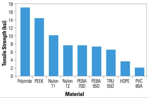
When working with balloon and stent devices, the tube design and material of construction must be sufficient to resist burst pressure. Standard engineering equations indicate a direct relationship between burst pressure and tensile strength. Thus, for a catheter tube of a given cross section, the relative burst pressure performance can be assessed by the tensile strength of various materials (see Figure 3). Materials such as PI and PEEK have the highest burst pressure performance of materials commonly used in vascular catheters.
|
Figure 3. This graph shoes the tensile strength of common catheter materials. |
Increasing the wall thickness, decreasing the tube diameter, or both can also increase burst pressure. Wall thicknesses are usually limited due to outside diameters limited by blood vessel size and the inside diameters required for sufficient working channels. Larger diameters result in stiffer catheter shafts, as noted from the rigidity formulas.
Because often only select lumens are pressurized, one approach has been to line specific lumens with high-performance materials, such as PI, while the remaining shaft remains a flexible polymer. This approach increases the burst pressure of the specific lumen in two ways: increased tensile strength and diameter reduction of the lumen. The modulus of the lumen lining material will typically be higher than the surrounding material; however, the resulting increase in rigidity is managed by selectively applying this material in a localized area within the cross section. This minimizes the increase in the cross-sectional moment of inertia that influences rigidity.
Often, working channels must also be sufficiently lubricious to allow devices to readily pass through the catheter shaft. In medical devices, the physical property most commonly used to define the lubricity of a device is coefficient of friction. A low coefficient of friction implies better lubricity in medical devices.
PTFE is well recognized as having the lowest coefficient of friction of polymers commonly used in medical devices. However, PTFE is not processible by melt extrusion and lacks many of the mechanical performance properties necessary for catheter shafts. PTFE is therefore used as a liner within shafts. Yet, it is highly chemical resistant and requires chemical or plasma etching, and a bonding layer for adhesion to the outer catheter layer. Typically, this is performed as a manual operation.
Trilayer extrusion is a process by which three extruders simultaneously extrude unique layers around the circumference of the catheter shaft during extrusion. Melt processible polyethylene has an outstanding coefficient of friction and is used as an alternative to PTFE for the lubricious inner layer. The middle layer serves as a bond between the lubricious polyethylene to the soft, outer thermoplastic layer, which is commonly PEBA, nylon, or polyurethane. While polyethylene has a higher coefficient of friction than PTFE, it provides a harder surface that is less susceptible to plowing or gouging of devices into the surface, particularly around sharp turns.
Combination Extrusions
Prior to the current extrusion technologies available, design engineers have employed hand-layup fabrication of discrete catheter segments to achieve unique properties in different sections of the catheter shaft. Guide catheters used for the delivery of stents, balloons, and other such devices in the body are a common example of this approach.
Conventional guide catheters consist of three distinct layers. A braided steel matrix is sandwiched between an inner PTFE layer and an outer thermoplastic layer that is often engineered from nylon or PEBA. The PTFE inner layer provides lubricity to facilitate device passage. The stainless-steel braided layer enhances torque transmission and shaft support. The thermoplastic outer layer provides a smooth surface against the blood vessel wall.
Variable flexibility of the outer thermoplastic layer from the proximal to distal end has been achieved by hand-assembling discrete extrusions of different durometer over the braided layer and bonding them together with thermal or adhesive techniques. In some cases, the steel braid pitch is varied to modify the stiffness of the shaft.
To produce this assembly, the PTFE layer has to be manufactured via ram extrusion, a pressure-sintering process that often requires the expertise of a specialty vendor. This, along with the separate braiding operation and hand assembly of multiple tubes for the outer layer, results in a multiple-component, labor-intensive process subject to considerable quality and validation challenges.
With today’s extrusion technologies, guide catheters can be manufactured in a continuous process to create a fully integrated composite shaft. The PTFE layer is replaced by a trilayer extrusion, with lubricious polyethylene on the inside, a bonding layer, and thermoplastic on the outside. Stainless-steel wire is then continuously braided over this extruded tube. Thermoplastic is extruded over the braided layer, penetrating the braid and bonding to the outer surface of the inner tube.
Variable flexibility of the outer layer is achieved by intermittent extrusion of variable durometer polymers along the length of the shaft. This approach offers several benefits over conventional manufacturing of guide catheters. First, the use of all melt-processible thermoplastics results in an integrated bonding between layers and ensures reliable shaft performance. Continuous variable durometer extrusion of the outer layer eliminates kinking at bonded segment interfaces in traditional designs. Elimination of discrete components and manual operations improves quality and validation. Finally, a continuous manufacturing process offers substantial cost savings.
Conclusion
Three primary variables affect catheter shaft performance: materials, design, and process. The polymers of choice are well established, and the number of new polymers invented by chemical companies is limited. Catheter shaft dimensions are typically constrained by blood vessel walls and internal working channels. These constraints are increasing as device companies seek to reach smaller, more distal regions of the vascular system and deploy more devices.
Current extrusion process technologies continue to develop, allowing designers to reach new frontiers in catheter construction. Multiple materials throughout catheter cross sections and along the length, and variable cross-sectional configurations along the length provide highly tailored performance shafts. Using continuous processing methods, these solutions also offer cost-effective alternatives to manual assembly methods used to date.
Byron Flagg is a mechanical engineer with Putnam Plastics (Dayville, CT), where he has worked for nine years. He is a graduate of Rensselaer Polytechnic Institute and holds a bachelor’s degree in mechanical engineering. He also earned an MBA from Boston College. Contact him at [email protected].
About the Author(s)
You May Also Like
