Integrating Automatic Leak Testing with Assembly Cuts Costs
April 17, 2005
Originally Published MPMN April 2005
PROFILE
Integrating Automatic Leak Testing with Assembly Cuts Costs
Molecular diagnostics firm boosts output for lab testing
|
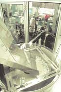
Open-ended cap blanks enter the assembly and test machine from a centrifugal bowl feeder. |
When the very reason a product becomes successful starts threatening its continued success, something has to change. For Gen-Probe Inc. (San Diego, www.gen-probe.com), a developer of genetic diagnostics for disease testing, that happened when its newest test for sexually transmitted diseases proved so sensitive that it could respond to specimens opened for similar test processing elsewhere in the lab. Solving that problem by inventing a new type of penetrable sealed cap for specimen tubes promptly led to another problem. The cap worked so well that rising customer demand for its use in other Gen-Probe assay kits promised to exceed the company’s ability to produce and test them. An advanced system integrating automated assembly and testing became an urgent priority, not only for increasing volume, but also for cutting costs.
The company’s Aptima Combo2 assay is believed to be the first to provide simultaneous detection of Chlamydia trachomatis and Neisseria gonorrhoeae infections using urine or ocular fluid samples. Its performance is equivalent to first-generation tests that required intrusive and sometimes painful swab samples.
Detecting both diseases from one sample also serves the user laboratories’ pressing need to improve their productivity. The assay portion of the test procedure, in which the patient sample is processed for diagnostic conclusion, typically involves a 5-hour sequence of heating, mixing, separating, applying reagents, and reading results with special instruments.
The assay uses the company’s patented technology for nucleic acid amplification, called transcription-mediated amplification (TMA). This greatly enhances sensitivity over previous versions of the test. Along with this improvement came a big problem, recalls director of OTS manufacturing engineering Dale Camper, “With our [previous] system, physicians would place swab specimens into capped tubes that were supplied preloaded with fluid-transport media,” he says. “Handling naturally caused swab and fluid to slosh around inside the tube, often forming bubbles beneath the cap. When the cap was removed in the lab, the bubbles would pop and release tiny droplets into the air. These aerosols were far too small to register on nearby assays, much less have any effect on lab personnel. However, Aptima with TMA could pick up these tiny aerosol traces and signal a false rRNA detection.”
|
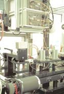
Two IDC M-1045 vacuum-rise leak detectors (above) simultaneously test two caps on pallets passing below. |
Rather than compromise the assay’s sensitivity, the company’s scientists focused on eliminating the need to uncap the tube. Taking that approach led to a new penetrable cap design comprising a hollow cylinder with a membrane seal across its midplane, another seal across its outer end, and a filter pile packed in between. The cap remains on the tube but allows assay samples to be drawn by inserting a pipette through the seals and filter. The snug fit between seals, filter, and pipette prevent any aerosol emission, and the resilience of the filter pile automatically recloses the hole left after the pipette is withdrawn. These features also isolate the specimen in the tube from any airborne contaminants in the area.
The redesigned cap became part of a broader concept called direct tube sampling (DTS). “Then came another problem,” Camper says. “Early users of Aptima immediately began urging us to use the same type of specimen tube and cap for other assay kits. Projections for that suggest we’ll be making 50% more of these within a year, and probably averaging year-over-year gains of at least 20% for a while after that. So now we needed a way to produce the caps in much higher volume yet test each one for seal integrity.”
The Aptima cap starts out as an open-ended cylinder molded of white polypropylene, approximately 16 mm in diameter and 17 mm long, with a 1.6-mm-wide flange around the inside circumference at mid-length. This internal flange provides the seat for the internal membrane seal, which is a disk made of aluminum foil laminated onto a polyester-polyethylene film. The film reinforces the foil’s vapor barrier while providing a surface that will heat-bond to the cap’s flange by induction welding under pressure. During cap assembly, the inner seal is mounted first, then a strip of filter pile material is coiled and inserted above that seal, and a second foil-disk seal is applied across the cap’s upper end to lock the filter in place. The cap’s lower end below the welded seal is molded with female threads that screw onto the sample tube.
In the initial production of Aptima kit components, all caps were made essentially by hand. After the inner seal disk was peeled off a Mylar backing and welded in, each cap was leak tested to verify the sealing integrity of both the foil disk and its perimeter weld. For that, the caps were taken off-line manually and loaded into a ten-up fixture, which applied 10-psi air pressure against the underside of the middle seal. Pressurizing and stabilizing took 2.5 seconds, then the test measurements took another 2 seconds. Acceptance was limited to batches that allowed a pressure loss no greater than 0.007 psig. Accepted caps were carried back to the assembly line for manual addition of their filter pile and upper seal.
|
Caps seated on in-line pallets departing the first seal insertion stations (left) immediately pass through leak testing (right); rejected caps are denied further assembly, saving additional materials. |
“As soon as we realized the increasing volume potential,” Camper says, “we knew we were in trouble. Our four manual assembly stations, rotating five people, could produce no more than 15,000 caps per week. The 4.5-second leak test, which lost additional time in the manual transfer from and back to the assembly line, was far too slow, yielding about 20 caps per minute at best.”
Returning to the local systems integrator that built the Aptima assembly equipment, PhedCorp (Anaheim, CA; www.phedcorp.com), Camper sought a fully automated alternative that would combine assembly and testing into a faster process that eliminates the need for in-process manual handling.
“At first, we simply envisioned an automatic version of the manual pressure test that we had been using,” he recalls, “but the vendor that supplied that tester to PhedCorp couldn’t seem to come up with faster speeds.”
Gen-Probe evaluated several alternative vendors and selected InterTech Development Co. (IDC; Skokie, IL; www.intertechdevelopment.com) to provide the leak testing system. By that time, PhedCorp was well along in establishing the new assembly-test machine as an in-line system that would receive cap blanks from a centrifugal bowl feeder; load them into conveyor pallets in pairs, threaded end down; then advance the pallets through a sequence of stations including a leak testing station positioned immediately after induction welding. To keep machine design as simple as possible, all assembling and test functions would be performed from above the pallets.
“One of IDC’s first contributions was the observation that the caps would be arriving upside down for the kind of pressure test we envisioned,” Camper notes, explaining why. “Although Aptima sample tubes are not inherently pressurized, we knew they often would be shipped by air. It made sense that our cap seal tests should be pressurized from the open end to simulate the pressure differential likely to build up inside the sealed tubes due to lower ambient pressures during flight. But in our machine, the open end faced the wrong way.”
“Air shipment considerations also shaped our 10-psi test pressure,” he adds. “We researched Federal Express temperature and pressure standards for cargo holds in various types of aircraft flying at different altitudes, calculated the highest probable differential, and added a conservative margin of safety to arrive at our spec.”
To avoid adding complexity to the machine PhedCorp was developing, IDC proposed replacing the pressure test, which would have to be performed from below, with a –10-psig vacuum test performed from above. In addition, switching to vacuum technology would make it easier to meet Gen-Probe’s 1.5-second test cycle time requirement, in part because a vacuum inherently requires less stabilizing than pressurization does. Also helping to cut stabilization time, the vacuum environment prompts quicker fixture-to-part sealing.
Further promoting faster cycle time, IDC customized its M-1045 leak detector, a computerized pressure-decay instrument, to measure low-level vacuum rise in low-volume test parts, and provided guidance for PhedCorp’s design of the new machine’s leak testing fixtures for best possible coordination among instrument, fixtures, and test circuit. When the fixture descends and seals against the top of the cap, it encloses a test cavity slightly less than 0.5 cm3 from which the M-1045 draws its vacuum. Leakage would reveal itself by a rise of the vacuum. In order to provide a volumetric leak-rate measurement traceable to an industry standard that accounts for test-part volume, the M-1045 converts its vacuum-rise measurement into standard cubic centimeters per minute and reports that value numerically on its front-panel display. Gen-Probe’s previous acceptance limit of 0.007 psig, programmed into the M-1075 via a front- panel keypad, converts to 0.343 sccm.
|
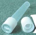
Completed caps, designed to keep specimen tubes closed, feature a midplane seal (right) and a top seal (left), with a special filter between the seals. |
Although the instrument continuously displays real-time test vacuum and leak-rate values, front-panel lighted indicators also show amber for test in progress, green for accept, and red for reject, providing an immediate visual alert requiring no operator judgment. More important for integrated assembly/test systems, the instrument responds to and shares its information with the assembly machines’ PLC through its bidirectional RS-232C interface.
Two M-1045 instruments mounted side-by-side within the PhedCorp machine test two caps simultaneously, letting accepted caps proceed to completion. Whenever a cap fails its leak test, the M-1045 tags it electronically to inhibit further assembly, avoiding waste of the filter and second seal that otherwise would be added downstream.
Filter pile and top seal are inspected by machine vision for proper placement, and likewise tagged to guide further machine activity. At the end of the line, separate accept and reject chutes arc down over the passing pallets, and based on electronic tagging from the leak tester and machine vision system, puffs of air from below blow each cap into the appropriate chute for collection in separate bins.
“So far, we’ve not calculated the material cost savings from inhibiting the completion of caps rejected in the leak tests,” Camper notes, “but we know some savings exist because production records maintained in the system indicate a reject rate of between three and five percent, with one-third to one-half of them recorded at the leak testing stations. Among the leak rejects, we’ve had instances where the reject was attributable to wear on the fixture seal rather than a leaking cap, and we were able to catch it very early due to the IDC instrument’s seal-check feature, which detects the slightest change in seal integrity.”
PhedCorp’s president Bassam Poullath says, “The other vendors we looked at were more price-attractive, but IDC offered a true turnkey test station that we could simply drop into our machine, very user-friendly with very good documentation. The others left a lot for us to add or figure out before we could put the tester into place. IDC also helped us with designing the method of sealing our test fixture to the test part. . . they shared their concepts, provided photos and drawings of other fixtures they designed for similar applications, and basically showed us what we needed to do. That made it easy to achieve a seamless integration.”
Copyright ©2005 Medical Product Manufacturing News
You May Also Like


