Medical Device & Diagnostic Industry Magazine MDDI Article Index
Medical Device & Diagnostic Industry Magazine Originally Published MDDI January 2006 BAR CODE TECHNOLOGY Before implementing a bar code system, medical device manufacturers should know the basics of bar code technology. By Andrew Zosel and Niels Wartenberg
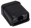
Since the 1970s, bar codes have provided a reliable, inexpensive form of machine-readable identification. Although bar coding has numerous benefits, its primary function is to error-proof the data-entry process. Studies show that one out of 300 manually keyed entries results in an error, but only one out of 3 million scanned entries using a Code 39 bar code results in an error. Clinical analyzers with embedded bar code readers provide a good example of how bar coding can reduce errors and save time. With an embedded bar code reader (see Figure 1), an analyzer can identify each sample, determine what test needs to be performed, and identify the necessary reagent. The entire test is bar code verified, and the information is automatically uploaded to the central laboratory's database. Without the bar code and reader, the information would have to be keyed in manually, which can reduce efficiency and increase errors. The Basics of Bar Coding
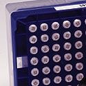
Before implementing a bar code system, it's important to understand different types of codes and how bar code scanners work. A linear bar code can be described as a series of parallel bars and spaces, referred to as elements (see Figure 2). The bars, or dark elements, of the code absorb light and the white spaces reflect light. Width or height patterns defined by the symbology are used to encode the data within the symbol. The code's data are extracted using a scanner with an integral light source. Two-dimensional (2-D) codes can be grouped into two different categories: stacked linear and matrix. Stacked-linear codes consist of rows of width-modulated bar codes stacked on top of each other. Each row is the same length and resembles a single-line bar code. Matrix codes are 2- D patterns of data cells in the shape of tiny squares, circles, or polygons (see Figure 3). Unlike linear and stacked bar codes, matrix codes cannot be decoded by a laser scanner. They must be read with an image-based reader, which functions similar to a digital camera.
Bar Coding Applications Clinical Analysis. There are two types of bar code applications in clinical analysis: specimen identification and consumable identification. The first type is used for bar coding patient samples, or specimens, collected in healthcare settings (see Figures 4 and 5). Typically, this application uses a linear code such as Code 128, Code 39, Interleaved 2 of 5, or Codabar. The bar code's information is called a specimen identification (specimen ID). It is a unique identifier enabling the laboratory information system (LIS) or hospital information system (HIS) to identify a specimen and associate it with a particular patient.
When a specimen is placed on an analyzer, the bar code reader decodes the specimen ID. The decoded ID is then sent to the LIS or HIS where two pieces of information, the specimen and analyzer IDs, are stored. Based on the IDs, the LIS queries its database for applicable tests to be performed by the analyzer. Test requests matching both parameters are then downloaded to the analyzer, providing information needed to perform clinical analysis on the specimen. Once the analysis is complete, the result is sent to the LIS to be posted in the database. Physicians can then access patients' test results without waiting for paper reports from the lab. This process is called a closed-loop application because access to a shared database allows the specimen ID to contain only a unique ID, or license plate, pointing to a location in the database.
Manufacturers are exploring ways to use 2-D codes for open-loop applications, in which a shared database is not practical. In 2-D coding, the code is either placed on the specimen tube itself or on accompanying paperwork. The code could contain all pertinent test requests and patient information. It could also enable automated entry into the database at the analysis location without cross-referencing another database. The second common bar coding application in clinical analysis is consumable information, mostly related to reagents. The bar code identification of non-test-specific bulk reagents can help provide a complete record of test results, but it is more important to track test-specific reagents. Most reagent packages contain a linear bar code that identifies the type of test and a pack serial number or other unique identifier. Although reagent manufacturers try to make each lot, or batch, of reagents as similar as possible, variations in raw materials prevent lots from being absolutely identical. As a result, it is common for analyzers to require information regarding lot-specific values for a number of parameters. In modern laboratories, this information is often stored on disks, bar coded cards, or other media separate from the reagent container itself. With improved 2-D imagers, all reagent data can be printed directly on the reagent container. Because of their scalability and high information density, 2-D and QR codes, which are capable of handling all types of data including numeric and alphabetic characters, are particularly well suited for such applications.
Medical Device Manufacturing. The medical device industry was quick to adopt 2-D codes and readers. The industry's need for traceability and process control has made use of matrix-based 2-D codes widespread (see Figures 6 and 7). For products such as pacemakers, synthetic joints, and stents, using a directly marked, unique identifier enables manufacturers to create and maintain production histories of each assembly and its major parts. Some manufacturers have implemented full tracking in which a part is marked with a unique ID. During production, the mark is read and the information regarding the manufacturing process and the test results is added to the part's data file. If a performance error is found, manufacturers using bar codes for unit-level traceability can retrieve information about results from all tests, components used, and operators involved.
Matrix-based 2-D codes can carry the pointer, or link, to all these data on devices as small as arterial stents or catheter tubing. New 2-D imaging devices provide instant information on production, from incoming materials to final build, with a permanent data pointer for each device. Understanding How Bar Code Readers Work Laser scanning is a common method for decoding linear bar codes. As the laser spot (which moves so fast it appears to the eye as a line) passes over the dark and light elements of the bar code, a photodetector measures the amount of light reflected back by each element (see Figures 8 and 9). This photodetector converts the light energy into electrical energy, which is transformed through signal processing from an analog to a digital signal. The digital signal is then decoded based on the symbology formulas. Once decoded, the data can be entered into an LIS, or the bar code reader can perform logical tasks based on the decoded data. Linear imagers are similar to laser scanners because each has a field of view one pixel tall and many pixels wide. Neither of those readers can decode 2-D images because they only process counts across a single line.
An array imager is needed to read 2-D symbols. These imagers use an array, or matrix, of gray-scale pixels to process symbols. An embedded array of light-emitting diodes (LEDs) illuminates the image, instead of a single laser diode or a single row of LEDs. A charge-coupled device (CCD) or complementary metal-oxide semiconductor (CMOS) collects the photon energy reflected back from the scanned object. A semiconductor converts the photon energy into an analog signal, which is then converted to a digital gray-scale value.
In order for a linear imager to read a bar code, the laser's field of view must be aligned perpendicularly to the code's bars and spaces. The bar code's alignment and the direction of travel are important when using a linear bar code reader. However, because array imagers process images two dimensionally, the code or symbol alignment is not relevant. In general, an array imager is also more forgiving of poor contrast or symbol damage than a linear imager because it captures the entire symbol like a snapshot, rather than scanning the symbol one line at a time. Imager-based bar code readers are emerging as a more-attractive technology compared with laser bar code scanners. Until recently, a 2-D–capable bar coding system was not easy to use and was not cost-effective to implement. Most imagers were too large and expensive to use as a subsystem within a diagnostic instrument. However, new miniature megapixel imagers can read 2-D codes while solving quality and alignment problems for both small portable devices and large-scale instruments. Technology on the Leading Edge During the last four years, most array imagers have been manufactured using VGA (640 × 480) resolution with 307,200 pixels. Oftentimes, this design has forced instrument designers to choose between resolution and field of view. Miniature megapixel imagers, however, offer SXGA (1280 × 1024) resolution with an array of more than 1 million pixels, delivering a larger field of view without sacrificing resolution. These imagers can read up to 100 2-D or data-matrix symbols within a single image. They can also process data in real time. The large field of view enables an imager to read an entire rack of bar coded specimen tubes at a time, or read combinations of 2-D codes and linear bar codes in a single pass. By scanning large quantities and various types of codes at one time, the entire data-capture process can be faster and more efficient (see Figure 10).
Moving Parts versus Solid State. Laser scanners have moving parts, including a motor that moves a mirror to sweep a laser across an object. In comparison, imagers are a solid-state technology, consisting of semiconducting materials and components with no moving parts. Imagers illuminate an object with an array of LEDs and use a lens to focus the target image onto a CMOS or CCD image sensor. An LED also has longer life expectancy than a laser diode. For example, a laser diode has a failure rate of 120 per 109 hours. Comparatively, the LEDs in an imager have a failure rate of 3 per 109 hours. The failure mode of LEDs also tends to be more gradual, whereas laser diodes tend to fail without warning. Small imagers also enable technicians to scan linear bar codes and 2-D codes with the same bar code reader (see Figure 11). Through a combination of solid-state technology and an LED-based light source, megapixel imagers typically have a longer life span than laser diode scanners. Manufacturers can reduce bar code reader–related failure rates in the field by using these imagers in their instruments. This technique can minimize the need for on-site service and the bar code reader subsystem's overall cost.
The combination of a large field of view and compact size gives miniature megapixel imagers exceptional scan and mechanical envelopes, which provide greater mounting flexibility, easing embedding inside an instrument. Miniature megapixel imagers also may cost less than standard imaging devices. For example, the megapixel imagers are smaller and may cost $2000–$3000 less than traditional imagers designed for industrial applications and environments, such as automated production lines. Megapixel imagers are not without their limitations, however, and an industrial imager may be more efficient in the long run. Some megapixel imagers are best suited for static applications in which the bar coded object doesn't move while being scanned. Objects moving on a conveyor must stop in front of the imager or move at very slow speed for a megapixel imager to read the bar code. However, applications in which an operator is presenting products to the reader would be ideal applications for using a lower-cost reader with higher capabilities. Conclusion Bar code systems play an important role in the device and diagnostics industries because they help ensure product quality and safety. They also increase the integrity of data entry for automated instruments. New megapixel imagers are benefiting medical applications by making 2-D matrix codes more accessible. Reduced cost and smaller size provide other benefits of embedding these devices into clinical analysis instruments. The technologies available to manufacturers are constantly expanding. As devices grow smaller and less space is available for linear bar codes, bar code–reading technology will evolve to meet device manufacturers' needs. Andrew Zosel is a product manager for Microscan Systems Inc. (Renton, WA). E-mail him at [email protected]. Niels Wartenberg is an applications engineer at Microscan, and can be contacted at [email protected]. Copyright ©2006 Medical Device & Diagnostic Industry |
About the Author(s)
You May Also Like


