Sign up for the QMED & MD+DI Daily newsletter.
May 3, 2002
3 Min Read
.svg?width=850&auto=webp&quality=95&format=jpg&disable=upscale "Vision Sensor Improves Measurement of Suture Cuffs")
Originally Published MPMN May 2002
PROFILE
Vision Sensor Improves Measurement of Suture Cuffs
A system provides 100% inspection at high speeds
|
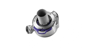
The In-Sight vision sensor transfers images to a vision-processing unit, where image analysis tools are used to gauge the part. |
Surgical sutures contain metallic cuffs that feature three inwardly bent tabs that act as a catch for capture needles as they pull the sutures through arteries.
To manufacture these parts, a company was measuring the diameter of the cuff openings manually. This process entailed skilled operators pushing upper- and lower-diameter limit pins through the opening. While this technique was capable of determining which parts were in and out of tolerance, it also had some disadvantages. It could take an operator up to 30 seconds per part. Also, tabs could inadvertently be opened up if an operator was not careful when inserting the pins, causing the damaged part to be scrapped.
To improve the process, Levin Engineering was asked to implement a machine vision system that would provide 100% inspection at higher speeds. According to company founder Steven Levin, ease of use was the primary factor in selecting a system for the job. "This was my first flight with [a] vision [system], and I wanted to find a product that didn't require writing code to develop the application," he says.
Levin selected the In-Sight from Cognex Corp. (Natick, MA). In-Sight is a high-performance vision sensor featuring an industrial-hardened vision-processing unit, a separate high-speed digital camera, onboard light control, built-in discrete input/output, and a standard VGA display output. To simplify application development, the vision sensor can be configured through an intuitive spreadsheet interface. The process involves selecting vision tools and parameters from drop-down menus using a handheld control pad. The spreadsheet then automatically generates tool results into worksheet cells, which are then linked together to perform measurement of the cuff openings.
The vision sensor is integrated along with a PC onto a tabletop bending machine. During the manufacturing process, each cuff is manually loaded with tweezers into a fixture. The machine first bends the three steel tabs inward as the part is positioned in place. At that point, a PLC triggers the vision camera, which looks axially at the cuff to capture an image of its opening. The image is immediately relayed to the vision-processing unit, where image analysis tools are used to gauge the part.
"Essentially, we're looking for a circle inscribed within a triangle formed by the three tab ends," says Levin. "The sensor's EdgeFind tool worked best in terms of accurately measuring the diameter of the cuff opening, which again is critical, since this end of the opening is what needs to catch the needle as it removes a suture."
If the opening diameter falls within the specified tolerance, the vision sensor displays a green LED on the user interface screen and the part is retrieved and transported to an assembly station. If the part fails the inspection, an audio alarm controlled by the PLC is sounded, alerting operators to retrieve and discard the part.
Since the sensor was installed in early 2001, it has been running for 16 hours per day without any failures. In addition to providing 100% inspection of the components, Levin notes a significant throughput improvement. "These parts are quite small, and it takes operators quite a bit of time to manually gauge the holes," he says. "With the vision sensor, it's really less than a second per inspection versus 30 seconds to do it manually." Levin also credits the sensor for its ability to provide exact measurement data for the holes, whereas pins can only provide information about upper and lower limits.
Copyright ©2002 Medical Product Manufacturing News
You May Also Like
Editors' Choice
.png?width=300&auto=webp&quality=80&disable=upscale)
Sponsored Content
May 23, 2024