January 1, 1999

Streamlining Innovation
At Interpore Cross International, a new software package was instrumental in helping engineers create an expandable spinal implant.
By Mark E. Apgar, Project Engineer, Interpore Cross International, Dublin, OH
Interpore Cross International had been designing spinal implants for years when it was presented with a new challenge: designing an expandable spinal implant. A neurosurgeon with a patent for a cage-type device had approached the corporation about developing his design. After careful consideration, Cross decided to accept the challenge and, in order to meet it, employed a variety of software programs to optimize the device's development.
The Challenge
Surgeons may opt to use an expandable spinal implant when performing certain types of spinal fusions. When spinal disks collapse, they can press on nerves, resulting in pain and loss of nerve signal to the limbs. In a spinal fusion procedure, a surgeon moves the vertebral bodies apart to relieve pressure on the nerves, then places bone graft material in the disk spaces between the vertebrae. An expandable vertebral device is used in place of a strut graft to hold the vertebral bodies apart and stabilize the spine while the bone graft placed inside the device takes hold, a process that usually takes several months.
The difference between an expandable vertebral device and a standard spinal cage is that after the expandable device is installed (in a compressed position) it can be lengthened to move vertebral bodies apart. The device is then locked in the expanded position. One of the challenges Cross faced in designing an expandable device was devising a locking mechanism that would hold securely. The device needed to be able to resist the dynamic loads placed on it—that is, be strong enough to support the weight of a person's head when used for treating cervical (neck) tumors.
Using the neurosurgeon's sketches, Cross created a solid model with Solid Modeling from Unigraphics Solutions Inc. (St. Louis). When the model was ready, Cross invited the surgeon to its offices. Under the surgeon's supervision, the engineers went through five different iterations of the design on the computer. Because Cross had parameterized the model, it was easy to make changes in response to the surgeon's suggestions. For example, when the surgeon wanted to change the angle of a flange to better meet the angle of a vertebral body, engineers simply changed a number and regenerated a model with the new flange angle. The surgeon was impressed with the speed at which Cross was able to incorporate his suggestions. Prior to this, he had worked out bugs by building and evaluating prototypes, which often took months to create.
How Did They Do It?
A spinal implant system consists of bone screws, hooks that attach to the vertebra, lateral connectors, and rods, as well as the tools needed to install these components. To be effective, a spinal implant must be strong, small, and easy to install. These were the guiding factors in the design of Cross's original Synergy spinal implant system, which has been on the market since 1995. For that design, Cross used an earlier generation of 2-D computer-aided design (CAD) technology to create drawings.
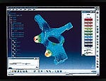
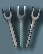 Engineers at Interpore Cross used Unigraphics CAD/CAM software to redesign the threads of a spinal implant screw. The software allowed design engineers to easily vary the model's parameters and run an analysis on the updated models until they found a thread design that met their requirements.
Although the 2-D CAD allowed Cross to create drawings quickly and to revise them easily, its effectiveness was limited. This is because Cross also used a finite-element analysis (FEA) program, Nastran, from MacNeal Schwendler Corp. (MSC), to simulate the performance of implant components. Nastran requires the use of a 3-D computer model to replicate real-world conditions. Working from the 2-D drawings, the Cross analyst had to recreate designs in 3-D in Nastran, a process that could take weeks and that limited the use of FEA. Despite its limitations, the system helped Cross fine-tune several components of the first implant system. It demonstrated the effect on stiffness and strength of changing bone screw variables such as pitch, ratio between major and minor diameter, and minor diameter taper. Using FEA as a guide, Cross created a new screw design in which the first five threads below the screw head are tapered for optimal performance.
Although these insights were valuable and helped Cross create a better product, the design of the original implant required a great deal of prototype testing. Here, too, someone had to work from the 2-D drawings—in this case, to program a CNC machine for cutting the metal prototype parts. Each prototype took 2 to 8 weeks to make.
Because Cross wished to reduce reliance on metal prototypes and allow greater use of FEA, the engineers decided to move from 2-D CAD to solid modeling. The benefits would be twofold: solid models could be transferred to Nastran, sparing the analyst the task of recreating designs for FEA, and it would allow Cross to replace metal prototypes with rapid prototyping techniques such as stereolithography. Cross also wanted parametric modeling capabilities, which would allow them to vary designs by plugging in new values for design variables. Because Cross creates a large number of screws, finding a program to simplify this task was a high priority. In a program such as 2-D CAD, laying out the threads was tedious and time-consuming. Cross wanted something more efficient and wanted the ability to export files directly into Nastran.
Cross found that Unigraphics' Solid Modeling met these requirements. The program's law curve capability proved to be an efficient way of modeling screws. Creating a path that a helix follows, a designer can simply attach the helix to a sketch of a screw thread, and the program removes the thread pattern from the solid mass of the screw. In addition, because MSC is a Unigraphics Solutions Alliance Program member, the company's products have a tight integration that allows solid models created in Unigraphics to be transferred to Nastran without data translation for the finite-element mesh.
Taking a Test Drive
The "test drive" of the new system was not as beneficial as it could have been because Cross did not have the new software from the very start of the project. The plan was to convert the corporation's original implant system from stainless steel into titanium. The engineers hoped they would be able to convert their original implant design to titanium without much reengineering; the fact that titanium is twice as flexible as stainless steel, however, complicated the matter. Because the engineering team did not have a solid modeler initially, they were required to do extensive prototype testing to investigate how the titanium threads that are inserted into bone would perform under physiological loading. This is when engineers decided to use the Unigraphics software to look for a solution.
The first step was to create the original screw design as a Unigraphics' solid model. Cross created a sketch, constrained parametrically, so that modifications would be easy to make later. Some of the parameterized values included major diameter, minor diameter, and pitch. The law curve function helped speed the process.
Next, Cross exported the solid model to Nastran to simulate the loads the screw would be subjected to inside a patient. Nastran results allowed engineeres to compare the performance of different thread designs. After analyzing one design in Nastran, Cross went back to Unigraphics to change the screw model by varying one or more of the model's parameters. Engineers then ran the analysis with the updated model, repeating the process until they had found a thread design that met their requirements.
New Product, New Process
Using the new software on the titanium conversion helped the engineering team complete the transition sooner than it normally could have. By allowing Cross to use FEA to solve the problems caused by the more flexible material, the software reduced the time-consuming prototyping process. Following this experience, it was clear to the engineers that solid modeling had a lot to offer, and that they had tapped only a fraction of its potential.
Designing the expandable vertebral cage would enable the engineers to use the full range of the software's capabilities. On this project, developed entirely in the new system, Cross also made good use of the ability to turn solid models into rapid prototypes. Cross used a stereolithography (STL) process provided by an outside service. When Cross wanted an evaluation part, the engineers simply converted a Unigraphics model to STL format (the conversion routine is included as part of Unigraphics), which is then read by the stereolithography machine. Cross would send an STL file to the service bureau via modem and in 1 or 2 days would receive a part. This was especially helpful when dealing with the surgeon, who liked to have solid model parts to examine.
As in other projects, Cross used Nastran to evaluate stresses on the various parts of the new device, which enabled design engineers to work out problems while the device was still in software, meaning fewer prototypes were needed. Although the engineers still had to build prototypes for final testing, by the time they built them, they were confident the prototypes would work.
Cross estimates use of the software saved more than $100,000 in prototyping and testing costs and reduced development time on this project by a year. Purchasing the new equipment (software and computers) cost $250,000, but Cross estimates it paid for itself after just two projects, including the expandable spinal implant.
Thinking in 3-DNew software packages are giving designers a more complete picture of their creations on screen, reducing the need for costly prototypes. By Sally Lane, MPMN Senior Editor Parametric Technology Corp. Delivers Enhanced Usability Continued user-interface improvements and automation tools are some of the Pro/ENGINEER development projects currently under way to combine usability and interoperability within the design environment. "The large focus on productivity through the user-interface improvements for Pro/ENGINEER Release 20 will continue to be enhanced as we move forward," says Laurie Stefanov, technical marketing director, Parametric Technology Corp. (PTC; Waltham, MA). Future development plans for Pro/ENGINEER will introduce enhanced usability for the engineering environment in conjunction with a Microsoft Windows—compliant user interface.
PTC will soon be introducing NC-EXPERT, which expands the usability of the programming tools of Pro/NC by focusing the functionality on the production machining of prismatic parts. NC-EXPERT allows numerical control programmers and process planners to take existing Pro/ENGINEER solid models and define them in terms of manufacturing features, such as "faces" and "pockets." Once the features have been defined and the process order specified, customized tool paths are easily applied. Another recent enhancement from PTC is the associative topology bus (ATB), which allows users in the continuum of PTC Solutions to access, share, and modify design information dynamically and concurrently. "Our customers work with different tools in the design environment, and we are trying to promote interoperability in this environment," Stefanov says. "For example, parts created in Pro/ENGINEER can now be associativity leveraged within Pro/DESKTOP, enabling users to optimize their work environment while maintaining time and effort invested in other systems." The ATB goes beyond standard data interchange by automatically updating the geometry, topology, and assembly structure in models created in other applications. The ATB will eventually facilitate associativity among other product design and development software, Stefanov says. SolidWorks 98Plus Promises Speedy Access to Assemblies The newest 3-D mechanical design software release from SolidWorks Corp. (Concord, MA) boasts more than 200 customer-driven enhancements, including user-interface improvements, detailing, assembly design, surfacing, and sheet-metal design capabilities. SolidWorks 98Plus's detailing tools make it easy to generate complete production-level engineering drawings that comply with major international standards. Users can create fully associative drawings—the model, drawing view, and assembly update automatically when modifications are made. The assembly design allows users to refer to the surrounding geometry, associating all of the relationships directly and propagating changes automatically throughout the design, eliminating the need to export parameters or build equations. A "lightweight" components capability allows users to open large assemblies up to 300% faster without loading any unnecessary data. The part-modeling feature enhances design flexibility and includes drag-and-drop capabilities, while the sheet-metal design capabilities allow designers to create in 3-D or "in the flat." "We are particularly excited about the new assembly features, including the ability to easily manage the entire assembly process with the enhanced configuration manager and the new lightweight components feature, which will reduce design time," says Paul McDonnell, a mechanical CAD coordinator for Automation Tooling Systems Inc. (Cambridge, ON, Canada). Instant Communication the Goal of OneSpace The ability to simultaneously communicate with customers, suppliers, and internal divisions is the key to developing sophisticated products vital to any company's success. Until recently, however, having real-time access to all of these groups was not possible. Now geographical distance needn't be a barrier to the creative process. CoCreate Software Inc. (Fort Collins, CO) has introduced OneSpace, a Web-enabled product development program that allows all members of a mechanical design team to interact in real time so they can share information and simultaneously work on and modify a model in electronic space. OneSpace, which targets the emerging virtual product development management (VPDM) market, functions on top of most 3-D computer-aided design (CAD) environments so users do not have to invest in new CAD technology to reap the benefits.
"The VPDM market is going to experience rapid growth during the next five years as manufacturers look for ways to leverage their intellectual capital in real time, instead of simply capturing design intent," says Dave Burdick, vice president of Gartner Group, a Stamford, CT–based market research firm. By giving companies the capability to bring together the right people at the right time, OneSpace allows for immediate problem solving, helping minimize delays. "With OneSpace, companies can make innovation a part of their culture by encouraging people from different disciplines to explore ideas together," says Tilman F. Schad, CoCreate's president and CEO. Structural Research & Analysis to Debut Three New Packages COSMOS/Works, a design-analysis program first introduced in 1997 that is tightly integrated with SolidWorks CAD, is getting a new twist. An updated version, COSMOS/Works 5.0, is due out this March from Structural Research & Analysis (Los Angeles). The updated version's capabilities will include gap/contact-in-assembly analysis, design optimization, new sparse matrix direct solver, optional UAI/NASTRAN linear static solver, transfer of motion loads from Dynamic Designer/Motion and Working Model 3D, and transitional meshing with mesh controls.
COSMOS/DesignSTAR, a new architecture that features a native Windows interface powered by the Parasolid modeling kernel from Unigraphics Solutions, is due to hit the market in February. It incorporates Spatial Technology's ACIS modeling kernel and an ACIS-to-Parasolid translator. In addition, it is compliant with object linking and embedding (OLE) for design and modeling programs, allowing associativity and enabling the designer to drag models from any compliant design program and drop them into COSMOS/DesignSTAR. The software has its own applications program interface, which will make it easy for third-party analysis developers, value-added resellers, and other users to add their own capabilities. It also allows designers to tile the screen and perform several analyses simultaneously. Due for release in January, COSMOS/Edge 3.0, based on the COSMOS/DesignSTAR architecture, is an associative design-analysis program for the Solid Edge CAD program. It allows for the analysis of assemblies as well as individual parts, real-time visualization of results, and the use of drag-and-drop techniques to select objects for analysis. The software also includes a Design Check Wizard to help users ensure a design meets all yield-strength criteria, and is capable of automatically preparing Web-enabled design reports in text and HTML with embedded virtual reality modeling language (VRML) and AVI visualization tools. Autodesk Unites 2- and 3-D Design At Baxter International's Fenwal Div., Autodesk has proven to be a real lifesaver—the software is helping designers to more quickly and efficiently develop specialized medical devices such as flexible and disposable blood-collection containers. "We need to refine our designs quickly and then move the devices on for clinical trials," says Tony Poventud, an engineer technician in the technical services group. "Autodesk software helps us answer this urgent call to save lives around the world." Release 14 Mechanical Desktop from Autodesk (San Rafael, CA) combines the 2-D capabilities of AutoCAD with advanced 3-D tools, including parametric feature-based solid modeling, nonuniform rational B-spline (NURBS) surface modeling, and assembly modeling. Component and assembly models are fully associative, and automatic interference checking can help pinpoint design errors. In particular, Autodesk allows Baxter's engineers to design parts to tolerances within 0.0001 in., Poventud notes. The software also makes it easier to share external files, while an MTEXT editor allows designers to annotate drawings and edit text easily, Poventud says. Mechanical Desktop's native AutoCAD compatibility also enables designers to easily create 3-D designs from existing 2-D data. Other features include a mechanical applications initiative that allows for finite-element analysis, sheet-metal design, NC programming, and analysis of kinematics, tolerance, and plastic flow, allowing designers to take their product from concept through production without ever leaving their desktop PC. Something for Everyone: CATIA Version 5 CATIA Version 5, a reengineered, next-generation, computer-aided design, manufacturing, and engineering program for both native Microsoft Windows NT and UNIX platforms, is the latest offering from Dassault Systémes S.A. (Suresnes, France) and marketed worldwide by IBM. The unique feature of CATIA 5 is its ability to be adapted to any level of design complexity and CAD/CAM experience. Occasional users with limited training can easily operate the Windows interface, while more experienced users can access its more advanced, process-based applications. CATIA Version 5 was designed to deliver intuitive part and assembly modeling. Generative drafting automatically creates associative drawings from 3-D mechanical designs and assemblies, while the real-time rendering applications produce photorealistic images by using technological material textures. The Knowledge Advisor feature assists designers in reaching informed decisions quickly.
CATIA Version 5 also provides easy-to-use designer-oriented part stress and modal analysis for early part prevalidation. Advance Smart Shape Designer tools allow designers to quickly create innovative, free-form shape design deformation. Advanced functions extend the shape- and surface-modeling functions to morphing complex multisurface shapes. "The thing to remember is that CATIA can benefit designers and manufacturers of everything from simple disposables to prosthetic devices," says Patrick Kieffer, who handles marketing communications at IBM Engineering Solutions. |
Software Focus is a new feature. If you are interested in having your product appear in an upcoming issue, please contact MPMN's editors by fax, 310/392-4920 or e-mail, [email protected].
You May Also Like
