Originally Published MDDI June 2006 METAL WELDING Engineers should understand the differences between resistance and laser welding and know when to use one or the other. Girish P. Kelkar
June 1, 2006
METAL WELDING
Medical devices use a variety of metal components that are often welded to form a secure and permanent bond. Options available for welding processes are limited because of certain constraints such as part geometry or metallurgy, or requirements such as autogenous welds (i.e., joining without adding a solder or braze) or the ability to make a single spot weld in a particular location. Such restrictions quickly reduce available choices to two processes, namely resistance welding and laser welding. These two processes are similar in that they are quite well suited to weld most medical alloys, but they vary in terms of part design and process control, and they form different types of bonds.
|
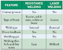
Table I. A summary comparison of resistance and laser welding process attributes. |
Selecting between these two processes is a difficult task that requires understanding the capabilities and limitations of both before making an informed decision (see Table I). This is especially true when the welding step is to be outsourced. In those cases, providing a robust design for the application becomes even more important. Engineers need to have a firm grasp of the fundamentals, including weld configurations, bond formation, process control, monitoring, and weld analysis, for both resistance and laser welding. Having such information will ensure that they will make the correct decision.
Resistance Welding
As the name implies, resistance welding uses electrical resistance to current flowing through the parts to generate welding heat. Current runs through two welding electrodes that are connected to the secondary of the welding power supply and complete the circuit. The two electrodes also provide the welding force, which is applied with the help of a weld head to ensure proper contact between the electrodes and the parts being welded.
A power supply converts an incoming high-voltage and low-current signal to a more usable (and safe) low-voltage and high-current energy. Currents ranging from 50 to 2000 A are typical for medical device applications.
Heat generated at the weld has multiple functions. The initial portion of the welding heat is used to burn away any organic contaminants at the weld interface—a puff of smoke created during a weld pulse is evidence of such activity. Contamination from finger oils and dirt in the atmosphere is minuscule and typically does not affect the weld. However, the presence of excessive black soot on the external surfaces or expelled from the weld interface would indicate contamination that needs to be removed before welding. Parts should then be cleaned with acetone and should only be handled with finger cots. The weld surfaces must always be free of contaminants such as mold release agents, stamping lubricants, and adhesives or polymers that creep into the weld zone. Naturally occurring surface oxides on most metals and alloys, including stainless steels and titanium, are not thick enough to impede welding.
|
Figure 1. Schematic showing the time diagram and waveform for resistance welding. |
A typical welding sequence (shown as a time diagram in Figure 1) starts with the moving electrodes coming down and applying the required welding force on the parts. After the mechanical systems stabilize (known as squeeze time), the weld pulse is fired by the power supply. Following the weld pulse, parts are maintained under the welding force and allowed to cool (hold time). It is during this cooling process that the weld develops its strength. After the hold time, the electrodes are retracted and the parts are removed. Depending on the type of power supply, the weld pulse can include an upslope, the weld time, and a downslope. Use of squeeze time and upslope prevent electrode sticking and arcing, whereas the downslope enables some flexibility in controlling weld temperature.
If the surface condition of the parts is inconsistent (leading to inconsistencies in contact resistance), a two-pulse weld can be used. In that process, the first pulse is used to condition the parts so that the inconsistencies are reduced. The second welding pulse then supplies the weld heat. The first pulse typically operates in the power mode with a current limit (closed-loop feedback units), supplying different amounts of energy in response to surface condition. Sometimes part geometry and material selection are complex, making it difficult to bring both parts to a molten or softened state simultaneously. In such cases, multiple weld pulses can be used to produce the desired result.1 The ability to simultaneously bring metals on either side of the weld interface to a molten or softened state is referred to as heat balance.
|
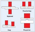
Figure 2. Weld configurations commonly used for resistance welding. Electrodes are shown in red. The weld location is shown as an ellipse with a dashed-line boundary. |
Weld Configurations. Resistance welding offers many choices for weld configurations; schematics are shown in Figure 2. In opposed-electrode welding, the two electrodes apply force to pinch the parts between the electrode tips. The opposed-electrode configuration is the most robust because the welding current has a direct and straight path to flow through. Figure 3a is a photograph of a cross-wire weld between a nickel wire and an alloy post.
If access is limited to one side, such as when welding tabs to a battery can, a parallel-gap or a step weld can be an option. Parallel-gap welds can be difficult to control because the welding current has the option to flow through either one or both layers. For situations in which the top layer is more conductive than the base, a step weld can be used to force the current to flow through the weld interface.
In configurations for which the parts to be welded are significantly different in size or electrical conductivity or both, it becomes difficult to produce the required welding temperature in both components at the weld interface. An alternative is to use a projection on the larger or more conductive component so as to provide better heat balance.
A projection can be stamped, coined, or machined. The size of the projection should match the size of the opposing part. For very thin aluminum foils welded to tungsten rod, roughening the rod surface by machining or by abrading it with sandpaper can create microscopic projections for welding. Welding thin foils and fine wires down to dimensions of 25 µm is possible with resistance welding because the majority of the heat is generated at the weld interface and enables the foil or wire to partly retain its structural integrity.
A unique aspect of the resistance welding process is that the weld location at the weld interface is shielded by the parts themselves, thus producing internal welds. A benefit of forming internal welds is that the weld zone is not exposed to air. Therefore, it does not require a shielding gas to prevent weld contamination. Such welds are also cosmetically appealing because they produce minimal disfigurement of the part surfaces and satisfy appearance requirements for surgical tools and diagnostic products. An inert shielding gas, such as argon (Ar), can be used to avoid surface oxidation.
|
Table II. Commonly used electrode materials for resistance welding. IACS refers to International Annealed Copper Standard and is used to express conductivity of nonmagnetic materials. |
Selection of a suitable welding electrode is also important because resistance welding is a contact process. Conductive Class 2 copper electrodes are used for welding resistive materials such as stainless steels and titanium. Conductive materials such as gold, copper, or platinum require resistive electrodes made of molybdenum or tungsten. Additional electrode choices are listed in Table II.
Improper selection of electrode material can lead to insufficient heating of the weld, electrode sticking, or surface contamination. If a configuration has no particularly suitable electrode, there may be an opportunity to introduce a third material to improve heat balance and take the focus away from the electrode material interface. For example, when welding a nickel tab to a titanium surface it may be helpful to introduce a stainless-steel foil between the two. The resistive stainless steel can help focus heat at the weld interface.
Types of Bonds. Resistance welding is unique in that the parts do not have to melt to form a bond; they only have to soften to forge together. Metal atoms on either side of the weld interface form a bond—as long as contaminants on the surface do not hinder the atoms that need to be in close proximity. A bond formed without the melting of constituents is called a solid-state bond. In most cases, bond lines are visible at the interface (as seen in Figure 3b) except when welding similar materials, in which case grain growth can occur across the interface. A solid-state bond is common when welding conductive alloys and refractory metals.
In addition to a solid-state bond, resistance welding can form a fusion bond where material on either side of the interface melts, mixes, and solidifies to form a weld. Fusion bonds are quite common during welding of resistive alloys such as stainless steels (Figure 3c). Even though the presence of fusion might be thought of as a preferred bond type, it is not often the case for medical devices where welding of dissimilar metals and alloys is common. A fusion bond between dissimilar metals can result in the formation of intermetallic compounds that can produce a brittle weld. It is in welding of dissimilar alloys, with a resultant solid-state bond, that resistance welding finds its niche. When welding dissimilar metals that have different melting points, the alloy with the lower melting point can form a braze on the higher-melting metal, as is seen during the welding of stainless-steel foils to a refractory pin (see Figure 3d).
|
Figure 3. Resistance welding methods. An opposed-electrode configuration may be best for nickel wire welded to an alloy post (a). Distinct weld lines (b) are easily visible in solid-state bonds. Resistive alloys, such as stainless steel, commonly need a fusion bond (c), where a weld nugget is formed. Braze formed by molten steel on a refractory metal pin (d) demonstrates how alloys with different melting points are bonded. |
Resistance welding is frequently used where either one or both components has plating on the surface. The plating can be used for improved corrosion resistance or to provide a good soldering surface. The plating alloy can act as a braze layer at the interface, or it can simply provide a good bonding agent to form a solid-state bond. A gold flash with a nickel barrier layer underneath is the most common variant. The gold layer can be easily welded to similar metals including copper, nickel, platinum, and palladium.
Resistance welding is also used where one or both components are tin (or solder) plated. The heat generated by current flow melts the plating and forms a solder fillet that produces a solder joint as it cools. Resistance welding is the only welding process that can produce all three types of bonds: solder or braze, solid-state, and fusion.
Process Control and Monitoring. In resistance welding, the electrical energy in the form of welding current flows from the power supply (or transformer) to the weld head where it makes its way through the electrodes, through the parts being welded, and back to the power supply to complete the circuit. The energy consumed by the weld can be quantified by measuring the voltage drop across the weld and the current flowing through the weld. The welding process has to satisfy both the energy equation and Ohm's law as follows:
Energy: E = V × I × t,
where V is voltage, I is current, and t is time;
Ohm's Law: V = I × R,
where R is the resistance.
If R is consistent between welds, then the electrical parameters and total energy delivered to the weld are also consistent. Any variation in R, whether caused by surface condition, bulk-material variation, or even electrode temperature changes, will result in corresponding changes in the electrical parameters and total energy.
Based on understanding the type of changes anticipated in R, the electrical parameters can be suitably compensated to produce consistent welds. Such compensation can be provided by closed-loop feedback systems that are set up to operate in current, voltage, or power mode.
Closed-loop power supplies are transistorized or linear direct current (dc), or high-frequency invertor types. Waveforms generated by such units closely resemble the schematic shown in Figure 1. Other types of power supplies used include alternating current (ac) sources and capacitor discharge (CD) units. These power sources produce a single pulse of energy that resembles a half-cycle ac profile. Neither of them typically provides closed-loop feedback, although some monitor electrical parameters.
A closed-loop power supply operating in current-control mode provides a programmed amount of current and allows the voltage to change based on changes in weld resistance. Changes in voltage should then be used as a monitoring parameter with statistical limits to provide process control. Likewise, current is monitored in voltage mode. In power mode, current, voltage, or both could be monitored.
Current-control mode has the ability to compensate for minor changes in oxidation levels. Voltage mode can be used to compensate for changes in electrode temperatures and shunting from neighboring welds or to prevent blowout of fine wires. Power mode can be effectively used to compensate for part-positioning variations.
In addition to monitoring electrical parameters, weld displacement also provides useful information. Displacement values can be effectively measured when either of the parts is a wire or has a projection. Measurement of weld displacement along with measurement of one electrical parameter can provide virtually complete information about weld quality.
Laser Welding
Laser welding uses a focused beam of laser light to melt and weld the two parts. Laser welding is a noncontact process and does not require any electrical connection to the part. A laser light source is monochromatic (single wavelength) and coherent (all rays are parallel). These properties allow the laser to be focused on a very small spot with sufficiently high energy density to melt metals. Laser energy is delivered in either pulsed or continuous mode. Continuous-mode welding is not common for medical devices and is not discussed in this article. During pulsed welding, the laser energy is delivered in a short, high-energy burst. Time scales are in milliseconds, and peak power is typically on the order of 3–5 kW. Pulses can be overlapped 80–95% to form a hermetic seal. Pulse welding is commonly used to seal titanium cans for implantable devices.
The laser source most commonly used for pulsed welding is an Nd:YAG laser, which emits a near-infrared wavelength of 1.064 µm. Internal configurations of the lasers include flash-lamp pumped rod lasers, disk lasers, and fiber lasers. Most metals that are not highly electrically conductive or reflective, such as titanium and stainless steels, absorb laser light reasonably well and therefore welding is not a problem.
Welding alloys of copper, gold, silver, and platinum can be difficult for several reasons. The alloys are reflective so it is difficult to couple the laser energy into the material to initiate the weld. Even if the light is absorbed, the high thermal conductivity diffuses the heat pulse away from the weld zone. The laser pulse must be programmed carefully to produce coupling and avoid excessive melting.
The typical welding sequence for laser spot welding is very similar to the resistance welding sequence shown in Figure 1. The parts must be brought together and held in place to ensure proper presentation to the laser energy, which is similar to the combination of force and squeeze time for resistance welding. The weld pulse can have an upslope, weld time, and a downslope for reasons similar to those for resistance welding. An upslope prevents excessive heating and expulsion; the downslope can be used to control the cooling rate of the weld metal.
Lasers are usually programmed by sectors in a single pulse. Newer units can have up to 20 sectors and can effectively produce any pattern needed, including upslope and downslope. Pulsed lasers also offer the flexibility to reduce energy in a series of pulses toward the end of a seam weld to provide a gradual transition. Even after the laser energy is turned off, the parts must be held together during a hold time to avoid disturbing the weld as the fused metal cools and then solidifies.
|
Figure 4. Schematics of weld configurations for laser welding. The fusion zones are shaded. Any of the configurations can be seam-welded with overlapping spot welds. |
Weld Configurations. Laser welding offers many choices for weld configurations; schematics are shown in Figure 4. Configurations include lap weld, butt weld, edge weld, and fillet weld. Also included is a schematic of a seam weld, which is essentially a series of overlapping spot welds. Any of the laser configurations can be used in a spot or seam weld configuration. Figure 5a depicts a lap seam weld.
In contrast to resistance welds where internal welds are produced, laser welds start from an external surface and work their way into the bulk of the materials being welded. Because the welds are external, only a small portion of the part to be welded has to be exposed to the laser.
Laser spot welds are formed in conduction mode or keyhole mode. In conduction mode, the laser energy interacts only with the surface of the metal or the weld pool. Heat generated by the absorption of the laser energy is transferred to the interior by conduction only. The weld-bead profile in cross-section is shaped much like a shallow bowl, as shown in Figure 5b.
|
Figure 5. Some examples of laser welds. A lap seam weld (a) shows overlapping pulses including the last pulse. A butt weld (b) between two components shows offset pulse location. Porosity in the weld is tolerable as long as the pores are trapped in the fusion zone, as in (c): a cross-section of the lap weld from figure 5a. Brazing formed by a lower melting alloy on a refractory metal wire (d) is actually a fusion bond. |
As the power density of a pulse is increased, the weld can transition to keyhole mode, where the molten metal is pushed aside by the weld plasma and the laser light reaches down into the weld. (Figure 5c shows a lap weld that appears to have transitioned to a keyhole mode and exhibits an inverted cone-shaped profile with a higher aspect ratio.)
One of the main challenges to laser welding is bringing the two parts to be welded into intimate contact. Laser welding is intolerant of air gaps, especially between small parts. As a rule of thumb, the maximum air gap should be less than 10% of the thinnest component. Use of fixtures is essential to ensure proper positioning and contact between parts. If holding the parts with fixtures proves difficult, the parts can be held together with tack welds prior to actual welding. Since laser welding is a noncontact process, it enables the designer to select weld locations that are not easily accessible for resistance welding electrodes and that require a fusion weld, as with feed-through welding. Laser energy can also be transmitted through a quartz window for welding inside an argon-filled chamber.
Types of Bonds. In laser welding, the absorbed weld energy is used to melt material across the weld interface. The molten material melts, mixes, and solidifies to form a bond. All laser welds in metals are fusion welds, as shown in Figures 5b and 5c. Solid-state welds are not an option. The presence of a fusion weld zone that is exposed to the environment presents a different set of challenges. The exposed melt pool has the potential to exchange atoms with the environment. For alloys containing volatile elements, there is the possibility that some fraction of the volatile component can evaporate during welding.
Of greater concern is the loss of material from the surface. Any violent expulsion during the welding process can throw off small globs of molten metal known as weld spatter. Usually the volume lost is small, but the spatter can get attached to other portions of the medical device and cause an electrical short or a mechanical malfunction. Control of the weld pulse profile is critical to avoid weld spatter.
Welding dissimilar metals is more challenging because there is the potential to form brittle intermetallics in the weld pool. The metal combination chosen should form a solid solution. Evaluating the relevant binary-phase diagram provides such information. If intermetallics are present, an engineer can reduce any detrimental effect by offsetting the laser spot so that one of the metals is a greater volume of the fusion zone (see Figure 5b). If the melting points are dramatically different, one of the metals can be made to melt and braze over the other as with resistance welding (see Figure 5d). Even though the weld in Figure 5d is referred to as a braze, it should technically be considered a fusion bond because there is no added braze alloy and one of the components melts.
Another option is to introduce a third metal at the weld interface that is compatible with both components. A patented weld alloy has been used with high success when welding nitinol to stainless steel.2
Of great concern for medical devices is the ingestion of gaseous elements into the molten metal. The usual contaminants are nitrogen, oxygen, and hydrogen.
Among the medical alloys, titanium-based alloys are the most susceptible. Most titanium welding should be performed in an argon-filled glovebox where the oxygen level is maintained at below 10 ppm and hydrogen (present as moisture) is controlled to a dew point of –60°C. If there is a possibility that oxygen or moisture could be absorbed onto the surface of the components introduced into the glovebox, it is acceptable to bake the parts before they are put in the glovebox.
Oxygen contamination can be visually identified by discoloration of the titanium weld as the color changes from dull gray to shades of tan. A dark tan or blue discoloration indicates significant contamination. Oxygen contamination is also evident in the metallurgical evaluation of the weld sections.
Hydrogen contamination is challenging because it cannot be identified, even with optical and scanning electron microscopes (SEMs). Furthermore, hydrogen contamination can cause delayed cracking that is difficult to predict.
Some titanium welds, and the majority of laser welds on steels, platinum, and other medical alloys, are made in enclosures (for laser safety) but not necessarily in a glovebox. For such applications, the fusion metal is shielded from air by a gas. Again, the most common shielding gas is dry argon, which essentially flushes oxygen and nitrogen away from the weld zone. Shielding gas can be provided coaxially with the laser beam or as a cross flow. For either option, the goal is to flood the area around the weld with the gas. Shielding gas should not be introduced as a sharp jet because the stream could actually drag adjacent air into the weld, eject molten material, or cause rapid cooling that affects the microstructure or final weld-bead shape.
Process Control and Monitoring. Most modern spot-welding lasers offer feedback control to ensure that a programmed amount of energy is delivered to the weld. The feedback loop operates by leaking a small fraction of laser energy out of the laser cavity and comparing this energy with programmed levels.
It is important to note that this feedback is still within the laser cavity and does not reflect any changes to the actual delivered energy from changes in the delivery system caused by broken fibers, misaligned lenses, or dirty cover glass. Therefore, in addition to internal feedback, laser energy is periodically monitored with an external laser thermopile to confirm laser stability. A thermopile looks like a small hockey puck and measures the laser energy by converting it into heat and measuring the change in temperature.
Additional issues that could affect the weld include focus height and spot positioning, neither of which are diagnosed by the thermopile. Unfortunately, direct feedback from the laser weld itself is not yet available in pulsed laser welding.
Weld Testing and Analysis
Medical device welds are tested for strength; common configurations are pull, peel, and shear tests. Most engineers are familiar with the issues related to mechanical testing, but that is only half the story. The other half, often ignored, is the metallographic analysis of weld cross sections. Metallographic evaluation includes observation of weld micrographs with an optical microscope and an SEM. Optical micrographs reveal the presence of cracks, porosity, heat imbalance (uneven weld nugget). They also reveal bond type, whether fusion, solid-state, or solder-braze.
A strong bond formed with resistance welding is often presumed to be the optimal choice. However, solid-state bonds can be as strong and are actually more common in medical device welds. The only way to find out the bond type is to observe the weld cross sections. Cracks in the weld nugget or in its vicinity are not acceptable under any circumstances; however, porosity can be tolerated as long as the pores are trapped in the fusion zone (Figure 5c) and are not anywhere near the edge of the weld. If segregation of elements or contamination is suspected, then elemental analysis with an SEM can reveal additional details. Presence of cracks, porosity, and elemental segregation provides added clues to weld performance over the long term under operating conditions. Metallographic analysis is essential to gathering this information, which may not be reflected in the results obtained from mechanical testing.
Conclusion
Laser welding and resistance welding are commonly used bonding processes for medical devices. The two processes are similar in many ways. Both can make small single-spot welds and can be used to bond all of the commonly used medical device metals and alloys. Both can be done in a typical lab environment and process equipment can be easily placed in cleanrooms. Both have the ability to produce autogenous welds, i.e., weld the two parts directly without needing an additional material as in brazing or soldering.
However, there are also many differences. One of the main differences is the type of bond formed by the process. Resistance welding offers three choices: solid-state, fusion, and reflow solder or braze, whereas laser welding only produces a fusion weld. The second major difference is that resistance welding produces an internal weld. The method typically does not require shielding gas, but requires greater real estate on the part. By contrast, laser welding produces external welds for which only a small volume of material needs to be exposed but often requires shielding gas.
Resistance welding is a contact process suited to welding wires and thin foils. Laser welding is a noncontact process, suitable for welding in locations with limited access and for seam welding applications. Selection between the two processes should be done carefully. It is essential to keep in mind the capabilities and limitations of both to ensure a robust manufacturing process.
References
1. GP Kelkar, “Why Use Multiple-Impulse Resistance Welding? An Explanation of the Process and Its Heat Balance Mechanism,” Practical Welding Today 8, no. 6 (2004): 18–20.
2. PC Hall, 2005. Method of Welding Titanium and Titanium Based Alloys to Ferrous Metals, U.S. Patent 6,875,949 B2, filed March 19, 2003, and issued April 5, 2005.
Girish P. Kelkar is the owner of WJM Technologies (Cerritos, CA), a consulting firm that specializes in technology related to welding. Contact him via www.welding-consultant.com.
Copyright ©2006 Medical Device & Diagnostic Industry
About the Author(s)
You May Also Like
