Sign up for the QMED & MD+DI Daily newsletter.
Medical Device & Diagnostic Industry MagazineMDDI Article IndexOriginally Published September 2000 Tapered cylindrical products such as medical guidewires and tubing can now be measured automatically by laser gauge–based profiling systems.Jon Gamble and Jim Kimmet
September 1, 2000
14 Min Read
.svg?width=850&auto=webp&quality=95&format=jpg&disable=upscale "Profiling: The Missing Link in Measurement Technology")
Medical Device & Diagnostic Industry Magazine
MDDI Article Index
Originally Published September 2000
Jon Gamble and Jim Kimmet
Disposable medical devices such as guidewires and catheters are generally manufactured in high volumes, using sophisticated fabrication processes, yet in many cases the technology for measuring and inspecting these products has lagged behind a company's production capacity. Although noncontact laser measurement equipment for inspecting constant-diameter products has been widely available for some time, manufacturers of devices with varying geometries have been forced to measure multiple points using slow, labor-intensive, manual methods. Not only do such manual technologies inhibit productivity and lead to long product development cycles, they are often inaccurate. Laser profiling technology now offers the capabilities required to overcome such limitations for products that are cylindrically symmetrical.
WHAT IS PROFILING?
A profiling system typically consists of a noncontact laser diameter gauge, a mechanism for moving sample parts through the gauge's measurement window, an encoder, and a PC with appropriate software and interface cards (see Figure 1). During the profiling operation, a sample part such as a ground guidewire or tapered catheter tube passes through the diameter gauge. The axial position of the part is monitored while diameter measurements are acquired at multiple points along its length (see Figure 2). To provide 360° measurement coverage, multiaxis lasers can be used, or the scanner or sample can be rotated. Obtaining a detailed representation of the part in a reasonable amount of time requires that the gauge have a high measurement rate (see sidebar on laser gauge technology, below). The profiling system's acquisition software generates a graphical display of the measurement data on the user-interface terminal. The measured values are then compared automatically or manually to a user-generated specification template, providing rapid and reliable information for use in product sorting and in process feedback and control.
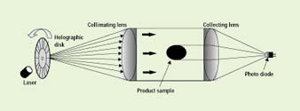
LASER GAUGE TECHNOLOGY The basic operating principle of a laser diameter gauge is quite simple. A laser beam is scanned across a measurement window using a rotating polygon mirror or a holographic disk, and then refocused onto a photodetector (see the first diagram). When a sample part such as a tapered tube or wire is placed in the measurement window, it interrupts the beam and casts a shadow on the photodetector. The duration of this shadow is then converted to a diameter measurement. By incorporating two sets of optics into one gauge, a dual-axis measurement of diameter can be obtained. Gauges currently on the market offer scan rates ranging from 100 to approximately 2800 scans per second per axis, depending on the number of elements in the polygon mirror or holographic disk and the rotational speed of the device. However, the scan rate may not be the gauge's true measurement rate. On many systems, because of variability in the geometry of the mirror, repeatability between individual scans is inadequate and multiple scans must be averaged to achieve acceptable results.
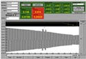
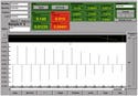
For example, a gauge that has a scan rate of 1000 scans per second may provide only 10 measurements per second because each 100 scans must be averaged to achieve system repeatability. The fastest commercially available gauge achieves a measurement rate of 2833 scans per second per axis with a repeatability of 4 mm. High measurement rates are critical in profiling applications because they produce higher-resolution profiles of moving parts than slower profiling systems do. The two profiles in the second diagram, for example, were produced by systems with differing measurement rates. The two small bumps located on the guidewire taper are easily missed on the profile at left, which was taken at a low measurement rate, while they are readily apparent on the higher-resolution graphic.
Profiles of a guidewire taken at 100 (left) and 2833 scans per second (right). Similarly, in the case of a bubble/taper tubing extrusion line running at 60 ft/min, a diameter gauge operating at 100 scans per second will obtain a measurement every 0.12 in., while a system operating at 2800 scans per second will obtain a measurement every 0.004 in. The profiles produced by the faster gauge would make it possible to monitor and measure short, rapid transitions that would be completely missed at the lower measurement rate. |
Applications for profiling are abundant in all areas of manufacturing. Any cylindrically symmetrical component or device that must achieve tight dimensional tolerances is a good candidate for the technology, but it is especially well suited for use with parts produced via turning, forming, grinding, and extrusion processes. The use of profiling in guidewire manufacturing and bubble/taper tubing extrusion is detailed later in this article.
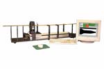 Figure 1. A guidewire profile measuring system (photo courtesy of Advanced Controlled Electromechanics Inc., Minneapolis).
BENEFITS OF PROFILING
Laser profiling systems offer many advantages over traditional manual measuring methods, which are both time-consuming and subject to error. Among these advantages are the following:
High Measurement Rates. With profiling, frequent measurements or even measurements of entire samples can be taken rapidly. For example, one guidewire manufacturer has reported that manual measurement of only critical features required 10 minutes of operator time per wire, whereas a profiling system can provide a profile of the entire wire in less than 30 seconds. By adopting profiling technology, manufacturers can achieve adequate inspection plans even for processes that require high sampling rates.
Improved Measurement Capability. When manual measurement methods are used, obtaining a satisfactory measurement capability—which is indicated by a repeatability and reproducibility (R&R) of less than 10% of the tolerance range—is always challenging. Furthermore, maintaining that R&R level as operators and inspectors move to other positions or leave the company requires constant training of new personnel. By eliminating operator-induced variability, a profiling system improves R&R and minimizes the impact of employee turnover on measurement capability.
Process Control and Capability. Closed-loop machine and process adjustment can be achieved by integrating a profiling system into a manufacturing line such as centerless grinding or extrusion. The operator is no longer part of the control loop and adjustments occur quickly and automatically. In addition, because of the improved measurement capability of a profiling system versus manual methods, the process adjustments will reflect true process parameters rather than measurement variations. On production lines where an automatic control loop is too difficult to implement, manual adjustment of the process will become more efficient with a profiling system because the measurements on which the adjustments are based will occur much faster. When either closed-loop process control or more-efficient operator adjustment is combined with the improved measurement capability provided by a profiling system, process capability (as defined by R&R) will also improve.
Data Retention. Profiling data are easily stored for production documentation purposes and are also readily accessible for SCADA applications, statistical process control, trending, and product and process validations.
Faster Startups. On production lines where each shift begins with an operator performing an iterative process of measuring a part and then adjusting the process, startup times can be reduced by using profiling. For example, in bubble/taper tubing extrusion, a significant amount of product goes into a waste bin while the operator cuts samples, makes measurements, and adjusts the process; cuts other samples to determine the effect of the adjustment; and so on, with each measurement requiring several minutes to complete. In contrast, with an on-line profiling system, the operator will receive real-time data on each sample so he or she can quickly determine the effect of small process adjustments and initiate production runs more rapidly.
Expanded Product Capabilities. In the example of the bubble/taper tubing, the reduction in startup times and the improvement in measurement capability resulting from the use of an on-line profiling system offer the possibility of using extrusion to produce more-complex parts with tighter tolerances, such as balloon catheters.
More-Efficient Process Validations. Because it collects greater amounts of more-accurate data than manual measurement techniques do, profiling can simplify and accelerate process validations.
Improved FDA Compliance. The higher sampling rates, improved measurement and process capabilities, better data retention, and more-efficient process validations that are achieved with profiling all facilitate a manufacturer's compliance with the quality system regulation and other FDA requirements.
Cost Savings. All of the factors above also contribute to reduced manufacturing costs. For example, a guidewire manufacturer achieved payback on its investment in profiling systems within six months because its gains in production efficiency reduced its need to add more grinding equipment and associated operators. In another case, an extruder of bubble/taper tubing that had required a staff of five inspectors to perform measurements on one extrusion line eliminated manual inspections by installing an on-line profiling system with sorting capability, thereby cutting labor costs while increasing overall productivity.
GUIDEWIRE MANUFACTURING
Medical guidewires are manufactured by grinding tapers on wire using a centerless grinding machine such as that shown in Figure 3. Typically, these tapers range from 0.014 in. at the proximal end of the wire to as small as 0.001 in. at the distal end. In the grinding process, the wire is fed between two grinding wheels with the smaller, regulating wheel tilted approximately 2° from its horizontal plane. This geometry induces a feed-through effect whereby the component is pulled through the machine by virtue of the grinding action performed by the wheels. The pull or feed rate is subject to many variables, including coolant quality, grinding-wheel diameter and sharpness, material hardness, and temperature. As a result, guidewire dimensions vary from part to part, and throughout a run. In one approach to reducing this variability, sensors are used to detect the motion and speed of the guidewire as it is being ground. Based on these data, the gap between the grinding wheels is continuously adjusted to produce a more-consistent feed rate and, therefore, more-consistent parts.
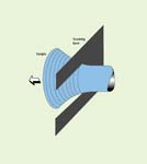
Figure 2. Typical laser profile of a tapered sample.
The guidewire manufacturing process can also be enhanced by the use of profiling systems. Manual measurement of guidewires is time-consuming because there are often multiple diameters, tapers, and transition points to be measured. Using a profiling system, a guidewire is simply loaded onto a motorized stage that passes through the laser gauge. With a high-speed gauge, the wire's diameter can be measured automatically every 0.001 in. along its entire length. As the diagram in Figure 4 indicates, one profiling system can serve several grinding machines, with the measurement results being fed back to the individual machines for process adjustments.
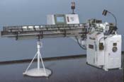 Figure 3. Centerless grinder for producing guidewires (Glebar Company, Inc.; Franklin Lakes, NJ).
Alternatively, a profiling system can be integrated with a single grinder either via a network or in-line. In such applications, as finished wires are being withdrawn from the grinding zone, they pass through the laser gauge. The resulting data are then used to make automatic grinder adjustments, thus compensating for any drift that may occur during a production cycle.
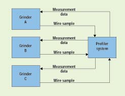
Figure 4. One profiling system can serve several grinders.
BUBBLE/TAPER TUBING EXTRUSION
In any medical tubing extrusion operation, variables that are difficult to control, such as variations in raw materials, will cause part dimensions to drift over time.1 For tubing with a constant diameter, correction for this drift can be accomplished by using an on-line noncontact laser gauge that measures the tubing diameter continuously and provides closed-loop adjustment of the extruder's puller speed and internal air pressure. On-line ultrasonic gauges can also be used, although this technology has not yet been widely adopted.2 Ultrasonic systems can automatically inspect and sort 100% of extruded tubing for wall thickness as well as outer diameter (OD). Closed-loop machine adjustment can also be implemented for a fully automated capability.
These standard measurement and control-loop systems cannot be used on bubble/taper tubing, however, because the diameter is always changing (see the sidebar, below). Thus, the operators are forced to obtain samples periodically, measure their critical features manually, and use the results to make machine and process adjustments. This manual procedure has been used successfully with the relatively simple extruded bubble/taper tubing used in products such as IV sets, which have wide specification tolerances, but the tubing used in balloon catheters must meet tighter tolerances than have been achievable on extrusion lines with manual inspection. An over-the-wire balloon catheter, for example, must have a precise OD at its distal end that matches the inner diameter (ID) of the balloon. The catheter shaft must also progress over its entire length to a larger proximal-end OD that precisely matches the ID of the manifold to which it is bonded. This diameter change on balloon catheters has typically been accomplished by assembling tubing sections with progressively smaller diameters, or by stretching or "necking" the tubing in a heated die. A key reason these expensive secondary processes have not been replaced by bubble/taper tubing extrusion has been the lack of a suitable on-line gauging technology capable of providing real-time profile visualization and closed-loop process adjustment.
On-line profiling technology now exists that addresses these gauging limitations. In systems designed for use with extruded bubble/taper tubing, a laser gauge feeds diameter data to a PC, an encoder signal provides position information, and the acquisition software generates a graphical display of the part profile. The software can also compare the part dimensions to a stored template and supply a signal to activate a sorting or marking mechanism. In addition, out-of-specification dimensions are flagged for the operator, and the system can provide closed-loop control of the extruder's puller and air pressure controller to compensate for dimensional drift.
THE EXTRUSION PROCESS
Bubble/taper tubing is produced by periodically changing the extrusion system's puller speed to create changes in the tubing's diameter. Diameter is increased by reducing puller speed, and the transition lengths between the various diameters are determined by the acceleration, deceleration, and time duration of the puller-speed changes. These parameters are generally controlled via an operator interface and puller control system.
The diagram below depicts a simple bubble tube. To form such a product, the puller first runs at a speed that results in the smaller tube diameter of section A. The puller then decelerates, producing the transition section B as it does so, and then momentarily maintains a lower speed that results in the larger-diameter section C. The last tubing segment, the transition section D, is produced by accelerating the puller back to the original speed. The cycle is then repeated to produce another part.
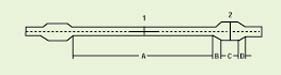
Schematic of a simple bubble/taper tube.
If the extruder's internal air pressure is adjusted appropriately during the puller-speed cycling, the wall thickness can be controlled as well. Increasing the air pressure as the speed is reduced and then reducing the air pressure as the speed is increased will result in a constant wall thickness.
In principle, this procedure seems simple, but in practice many mechanical, process, and material variables can affect the resulting tubing dimensions. For example, the viscoelastic properties of the melted polymer may vary between and within lots of resin, resulting in diameter and wall-thickness changes that require constant monitoring and process adjustments. Drafts, changes in room temperature, and changes in water-bath temperature all affect the rate of cooling of the melted polymer, which in turn affects the tubing diameter. Therefore, consistently producing bubble/taper tubing to tight tolerances requires state-of-the-art equipment and measuring tools.
CONCLUSION
Profiling technology can offer significant benefits to producers of cylindrically symmetrical components. Non-constant-diameter components that previously could only be measured by slow manual methods can now be measured rapidly, automatically, and accurately. Automated closed-loop control of manufacturing processes is also possible, resulting in more-stable production with higher yields and increased product quality. With the adoption of profiling systems, new product configurations become possible, process validations can be performed rapidly, and the product development cycle can be accelerated, contributing to faster product introduction and increased profits for medical device manufacturers.
ACKNOWLEDGMENTS
The authors would like to thank John Banyan of Glebar Company, Inc.; Jim Klapperich of RDN Manufacturing Company, Inc.; and Mike Nielsen of TSI Inc. for their assistance and input to this article.
REFERENCES
1. Hans W Kramer, Process Considerations in the Extrusion of Microbore Tubing, Medical Device & Diagnostic Industry 21, no. 1 (1999): 108–115.
2. Scott H Taylor, Advances in OD/ID Systems Benefit Medical Tubing Extrusion, Medical Device & Diagnostic Industry 18, no. 9 (1996): 102–109.
Jon Gamble is president of Advanced Controlled Electromechanics Inc. (Minneapolis), which supplies standard and custom manufacturing, measurement, and data collection equipment to the medical device industry. Jim Kimmet is a consultant to Advanced Controlled Electromechanics Inc. who specializes in medical tubing extrusion.
Back to the MDDI September table of contents | Back to the MDDI home page
Copyright ©2000 Medical Device & Diagnostic Industry
You May Also Like