Originally Published MDDI June 2006 NANOTECHNOLOGY Spintronic solid-state sensors have been used in industrial applications. New developments may make them useful for medical devices, too. Daniel A. Baker, Jay L. Brown, and Carl H. Smith
NANOTECHNOLOGY
Quantum mechanics states that electrons have two stable spins—up and down. With the advent of nanoscale fabrication methods, device companies are harnessing this knowledge to create devices. The technology, known as spintronics, has already been used to increase the storage density of hard drives.1 Spintronic sensors have been used for at least five years in industrial applications such as magnetic cylinder position sensors for robotics. This article reviews current medical applications of spintronic sensors, their construction and operation, design considerations, and possible future developments related to medical devices.
Spintronic Sensors
Military applications provided much of the impetus for developing spintronic sensors.2 In the medical industry, these sensors are used mostly as replacements for electromechanical magnetic switches such as ampule and microelectromechanical system (MEMS) reed switches. Spintronic sensors promise improved sensitivity and precision over electromechanical sensors, along with inherent reliability because of the absence of moving parts. Compared with other solid-state sensors, spintronic sensors offer more sensitivity and precision and are not damaged by large magnetic fields. Further, they are compatible with conventional semiconductor processing, which contributes to highly integrated sensor packages. Analog sensors can detect magnetic fields down to 0.1 nT, while digital sensors have precise magnetic operation points as low as 1 mT with repeatability better than 1%. For reference, the Earth's magnetic field is 0.05 mT, while typical magnetic resonance imaging fields are 1–3 T.
Spintronic sensors are becoming established in Class I medical devices such as air-conduction hearing aids. In hearing aids, the sensors are used to detect the use of a telephone or other electronic device and to automatically switch signal-processing modes.3 For example, the sensitivity of the sensors enables them to detect when hearing aid wearers are using cell phones. Manufacturers also may opt for the sensors because they are rugged and immune to vibration. Furthermore, their small size contributes to hearing-aid miniaturization.
Spintronic sensors are also used in Class III devices such as pacemakers, implantable cardiovertor-defibrillators, and neurostimulators. An important application is replacement of ampule and MEMS reed switches for magnetic activation of programming and special modes in implantable devices. Again, the absence of moving parts and small size make the sensors desirable for implant use.
Because of their unique physics, the operation point of spintronic sensors is more precise and repeatable than electromechanical sensors over the temperature and operating-voltage range. Unlike electromechanical sensors, the operation point of spintronic sensors is stable and repeatable over time, and the sensors are immune to mechanical shock or vibration. Such precision and repeatability—better than 1%—enable consistent operation at the required field while minimizing the chance of unintended activation.
Giant Magnetoresistors
The most common spintronic device uses an effect called giant magnetoresistance (GMR). GMR was first observed by researchers at Université Paris-Sud in 1988.4 Although the term giant seems incongruous for a device with nanoscale critical features, it refers to a large change in resistance (10 to 20% in commercial devices, and up to 100% in laboratory devices) when the devices are subjected to a magnetic field, compared with a maximum sensitivity of a few percent for other types of magnetic sensors.
|
Figure 1. A giant magnetoresistance sensor with no external magnetic field (a) exhibits high electrical resistance. When an |
GMRs comprise ferromagnetic alloys sandwiched around an ultrathin nonmagnetic conducting middle layer (see Figure 1a). The nonmagnetic conducting layer is often copper. Copper is normally an excellent conductor, but when it is only a few atoms thick, electron scattering causes copper's resistance to increase significantly.
This resistance changes depending on the relative orientation of electron spins surrounding the conducting layer. The spins in the magnetic materials above and below the conducting layer rotate when exposed to a magnetic field (see Figure 1b). Such exposure changes the device resistance so the structure can be used to sense an external field. Practical devices are often made of multiple layers of alternating magnetic and nonmagnetic layers to improve sensitivity.
Quantum Mechanics. To understand how GMR works on the atomic level, consider the following analogies: If a person throws a ball (analogous to a conduction electron) between two sets of rollers turning the same direction (analogous to parallel spin-aligned magnetic layers), the ball tends to go through smoothly. But if the top and bottom rollers turn in opposite directions, the ball tends to bounce and scatter. Alternatively, the GMR effect may be compared to light passing through polarizers. When the polarizers are aligned, light passes through; when their optical axes are rotated with respect to each other, light is blocked.
The resistance of metals depends on the mean free path of their conduction electrons, which, in GMR devices, depends on the spin orientation. In ferromagnetic materials, conduction electrons either spin up when their spin is parallel to the magnetic moment of the ferromagnet, or spin down when they are antiparallel. In nonmagnetic conductors, there are equal numbers of spin-up and spin-down electrons in all energy bands. Because of the ferromagnetic exchange interaction, there is a difference between the number of spin-up and spin-down electrons in the conduction bands. Quantum mechanics dictates that the probability of an electron being scattered when it passes into a ferromagnetic conductor depends on the direction of its spin. In general, electrons with a spin aligned with the majority of spins in the ferromagnets will travel further without being scattered.
In a GMR spintronic device, the first magnetic layer polarizes the electron spins. The second layer scatters the spins strongly if its moment is not aligned with the polarizer's moment. If the second layer's moment is aligned, it allows the spins to pass. The resistance therefore changes depending on whether the moments of the magnetic layers are parallel (low resistance) or antiparallel (high resistance).
Optimal layer thicknesses enhance magnetic-layer antiparallel coupling, which is necessary to keep the sensor in the high-resistance state when no field is applied. When an external field overcomes the antiparallel coupling, the moments in the magnetic layers align and reduce the resistance. If the layers are not the proper thickness, however, the coupling mechanism can destroy the GMR effect by causing ferromagnetic coupling between the magnetic layers.
For spin-dependent scattering to be a significant part of the total resistance, the layers must be thinner (to a magnitude of several nanometers) than the mean free path of electrons in most spintronic materials. A typical GMR medical sensor has a conducting layer approximately 3 nm (or one ten-millionth of an inch) thick. For reference, that is less than 10 atomic layers of copper, and less than one ten-thousandth the thickness of a piece of tissue paper.
Spintronic GMR Bridge Sensors
|
Figure 2. A spintronic sensor bridge. |
Figure 2 shows a photomicrograph of a typical GMR magnetic sensor, also known as a magnetometer. The thin metal-alloy films are vacuum deposited onto silicon wafers. Other manufacturing steps include thermal annealing, magnetic annealing, and photolithography. GMR resistors are generally patterned into serpentine resistors using photolithography. The serpentine configuration maximizes resistance per unit area. Maximizing resistance minimizes power consumption when the sensor is sampled.
In a typical sensor, four GMR resistors are configured as a Wheatstone bridge. A bridge configuration provides an easy-to-use voltage output that is proportional to the magnetic field applied but insensitive to any variations in the absolute resistance of the GMR device.
Two of the resistors are sensing resistors; the other two are reference resistors. The reference resistors are covered by a nickel-iron magnetic shield that measures 0.0004 in. thick. In response to an external magnetic field, the exposed sensing resistors decrease in electrical resistance while the reference resistors remain unchanged, causing a voltage at the bridge output.
The shield may also serve as a flux concentrator for the sensing resistors, increasing the sensitivity of the device and improving its spatial specificity. Because of the small geometries of spintronic sensors, flux concentration is especially effective and can increase sensitivity up to a factor of 100. Ampule reed switches rely on their electrical leads to concentrate magnetic flux, although variability in cut-lead length during assembly can change the magnetic operation point.
Spintronic sensors can generally be customized to the device manufacturer's needs for size, aspect ratio, and magnetic switch point. Smaller sensors tend to have lower resistance and less spatial specificity. More GMR material enables higher resistance and therefore lower peak power consumption. High-aspect-ratio sensors (i.e., long and narrow) tend to be more difficult for the manufacturer to saw into chips and therefore are more expensive.
|
Figure 3. Typical spintronic sensor output versus magnetic field. |
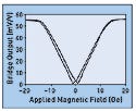
Electrical Characteristics. Figure 3 shows the output of a typical GMR multilayer versus applied magnetic fields. The output is inherently omnipolar, meaning it has the same change in resistance for a directionally positive or directionally negative magnetic field. This omnipolar change in resistance with the magnetic field is similar to the response of an electromechanical switch, with simplified electronics. The slope of the curve is proportional to the magnetic sensitivity, which is often expressed in millivolt per volt per oersted. When a magnetic field produces no further change in resistance, it is deemed saturated. The change in resistance from no field to saturation, usually expressed as a percentage of saturated resistance, is known as magnetoresistance. Hysteresis is the separation between positive- and negative-going curves.
Size and Packaging. Spintronic sensors are available in miniature semiconductor packages such as thin dual-in-line flat no-lead (TDFN) packages and micro small outline packages (MSOP). Parts are also available in die form for the most space-critical applications. The chips are connected using semiconductor wire-bonding equipment. Raw bridge sensor die can be as small as 0.020 in.2 and 0.008 in. thick.
System Considerations. Spintronic sensors are available as raw bridges and more recently as integrated circuits containing comparators and related functions to form a complete digital sensor switch replacement. Raw bridges can be used as continuous-field sensors, or some medical applications add analog or digital comparator functions to existing control circuitry. Accommodating an analog bridge rather than an electromechanical switch slightly increases control circuitry complexity, although this is offset somewhat by obviating the need to debounce electromechanical switch inputs. Designing control circuitry to interface directly to spintronic bridge sensors requires consideration of threshold detection and sampling.
The high sensitivity of spintronics means that preamplification is often unnecessary for a raw bridge. The bridge can be driven from a regulated supply with the output directly driving a comparator. The comparator can provide additional hysteresis if desired. Alternatively, the bridge can be powered directly from the battery, with the comparator threshold tied to the same battery voltage.
Integrated Electronics. In early 2005, sensors with integrated electronics (also known as digital sensors) were introduced for medical markets. The raw bridges are combined with low-voltage, low-power comparator and output circuitry on a single integrated circuit to provide a digital output. These devices are factory set for a particular magnetic operation point. Although these devices lack the flexibility of a raw bridge, they simplify the electrical interface and may facilitate the transition from electromechanical switches to solid-state sensors in medical applications.
Sampling. Because spintronic sensors are resistive, they draw current whenever power is applied to the resistors. Power consumption for a continuously powered bridge or digital sensor could be prohibitive. For example, a 5-kΩ bridge continuously powered by a 2.8-V primary cell would draw more than 500 µA, which would be entirely unacceptable in a battery-powered device. To minimize power consumption in battery-powered medical devices, sensors are generally sampled with a low duty cycle. Spintronic sensors are relatively fast because they have no moving parts and can typically be sampled in 10 microseconds or less. If a sampling rate of 10 samples per second were required, the duty cycle would be less than 0.01% and the average sensor supply current would be less than 0.1 µA, which would be negligible compared with control circuit power consumption. Although sampling functions are now performed in the control circuit, integrated circuits with on-chip sampling and power management along with sensor bridges are expected in the future.
The Future of Medical Spintronics
Spintronic sensor technology is expected to advance in coming years. Sensors are expected to get even smaller. Future GMR materials could provide higher sensitivity, higher linearity, and lower hysteresis. Sophisticated integrated circuits could incorporate on-chip sampling, signal-processing, and power management functions.
In addition to GMR, researchers are perfecting another spintronic structure, spin-dependent-tunneling (SDT) junctions. These devices provide very high sensitivity. Tunneling refers to the movement of conduction electrons through a barrier that they should not be able to get through. SDT junctions work by decreasing resistance of insulating layers, as opposed to GMR, which increases the resistance of conducting layers. Basically, spintronics is a bit of an upside-down world, in which insulators become conductors and conductors become insulators. Researchers have reported SDT magnetoresistive ratios of more than 70% using aluminum oxide tunneling barriers and as much as 355% using magnesium oxide tunneling barriers.5–8
An advantage of SDT devices is that they can have much higher resistance, up to the megohm range, so they require less power than GMR sensors. Higher magnetoresistive ratios provide higher signal levels. Furthermore, if devices with very high magnetoresistive ratios can be commercialized, they would offer switchlike characteristics without added electronics. This could enable further miniaturization. Potential medical applications include MRI, magnetocardiography, and eddy-current defect detection.
Long-range developments include spintronic biosensors for laboratory-on-a-chip systems.9 These systems use biochemical assays labeled with magnetic nanoparticles. Spintronic sensors are used in place of optical systems to detect magnetic nanoparticles as biological markers.9 For one approach, sequences of single-stranded DNA matching part of the target DNA are attached to a chip surface above a spintronic detector. Sample target DNA, present in the fluid surrounding the spintronic detectors, hybridizes with the chip probe DNA. Then label-probe DNA, bound to some nanomagnetic labels, hybridizes with the exposed portion of the target DNA. In this way, magnetic labels are selectively captured on the chip surface. Spintronic sensors determine the number of nanomagnetic labels captured, which provides the concentration of the biomolecules, cells, or bacteria.
Another intriguing medical application of spintronics is magnetoresistive random-access memory (MRAM). MRAM data are written by an electrical pulse that creates a magnetic field. The field flips electron spins in an SDT junction. Data are stored on one of the ferromagnetic sandwich layers and read as the junction resistance. MRAM has been called the ideal memory because it has the potential to combine some of the best attributes of different semiconductor memories: the speed of static RAM, the density of dynamic RAM, and the nonvolatility of flash memory. Several companies have made MRAM samples and demonstrators.10
MRAM has gained attention for its potential in mainstream memory applications such as small, more power-efficient cell phones and instant-on computers. For medical devices, MRAM may have the potential to combine the functions of multiple memory types to reduce size and power consumption requirements.
Conclusion
Spintronics has been called an unprecedented opportunity to define a radically new class of device.11 Spintronic devices are improving medical devices such as hearing aids and pacemakers with their reliability, size, and precision. The behavior of electrons is becoming practical, putting a new spin on medical electronics applications.
GMR sensors have already been proven in Class III medical devices, and SDT junctions are being developed. Spintronic sensors use nanoscale features to harness quantum mechanics. GMR sensors are fabricated using semiconductor processing and metallurgy and can be customized to a manufacturer's needs for geometry and magnetic switch point. Sensors are available with raw bridge outputs or as integrated circuits for digital switch replacement, and devices are available in very small packages or as bare die.
The speed of spintronic sensors enables them to be sampled to dramatically reduce power consumption. GMR sensors are expected to become smaller and more integrated in coming years as the technology advances.
In the long term, SDT junctions could enable higher signal levels, further miniaturization, spintronic biosensors for laboratories-on-chips, and MRAM as a universal memory.
Spintronics may be critical to the future of nanotech medical devices.
References
1. BA Everitt et al., “Vertical Giant Magnetoresistive Read Heads for 50-Gb/in.2 Magnetic Recording,” IEEE Transactions on Magnetics 41, no. 1 (2005): 125–131.
2. 2004 Technology Applications Report, U.S. Missile Defense Agency (Washington, DC: Department of Defense, 2005): 44–45.
3. RC Johnson, “Hearing Aids Given Nanotech Spin,” Electronic Engineering Times (Feb. 14, 2005); available from Internet: www.eet.com/news/latest/showArticle.jhtml?articleID=60400167.
4. MN Baibich et al., “Giant Magnetoresistance of (001)Fe/(001)Cr Magnetic Superlattices,” Physical Review Letters 61, no. 21 (1988): 2472–2475.
5. D Wang et al., “70% TMR at Room Temperature for SDT Sandwich Junctions With CoFeB as Free and Reference Layers,” IEEE Transactions on Magnetics 40, no. 4 (2004): 2269–2271.
6. S Yuasa et al., “Giant Room-Temperature Magnetoresistance in Single-Crystal Fe/MgO/Fe Magnetic Tunnel Junctions,” Nature Materials 3, no. 12 (2004): 868–871.
7. S Parkin et al., “Giant Tunnelling [sic] Magnetoresistance at Room Temperature with MgO (100) Tunnel Barriers,” Nature Materials 3, no. 12 (2004): 862–867.
8. S Ikeda et al., “Dependence of Tunnel Magnetoresistance in MgO-Based Magnetic Tunnel Junctions on Ar Pressure during MgO Sputtering,” Japanese Journal of Applied Physics 44, no. 48 (2005): L1442–L1445.
9. JC Rife et al., “Design and Performance of GMR Sensors for the Detection of Magnetic Microbeads in Biosensors,” Sensors and Actuators A: Physical 107, no. 3 (2003): 209–303.
10. SA Wolf, AY Chtchelkanova, and DM Treger, “Spintronics—A Retrospective and Perspective,” IBM Journal of Research and Development 50, no 1 (2006): 101–110.
11. D Awschalom, ME Flatte, and N Samarth, “Spintronics,” Scientific American (June 2002): 67–73.
Daniel A. Baker is president and CEO of NVE Corp (Eden Prairie, MN) and can be contacted at [email protected]. Jay L. Brown is vice president for sensors of NVE, and Carl H. Smith is a consultant for NVE.
Copyright ©2006 Medical Device & Diagnostic Industry
About the Author(s)
You May Also Like


