Sign up for the QMED & MD+DI Daily newsletter.
January 1, 1998
11 Min Read
.svg?width=850&auto=webp&quality=95&format=jpg&disable=upscale "Electrical Testing and Environmental Screening of Hybrid Microelectronic Devices")
Medical Device & Diagnostic Industry Magazine
MDDI Article Index
An MD&DI January 1998 Column
MICROELECTRONICS
Hybrid devices require unique testing to ensure reliability for medical applications.
Generic test and environmental requirements for hybrid microelectronics are defined in MIL-PRF-38534 and MIL-STD-883. While these two specifications outline the requirements and quality assurance provisions for the manufacture and certification of hybrid device circuitry and packaging, they are geared toward military and aerospace applications. Hybrids intended for unique medical applications, however, require testing standards different from those used in the military and aerospace industries.
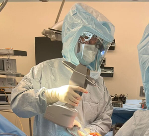
 Engineers perform electrical checks to obtain current, voltage, and frequency measurements that validate the electrical connection between the hybrid, socketing, and power supplies. Photos courtesy of (left) MET Laboratories (Baltimore) and (right) ED&D Inc./Educated Design & Development (Raleigh, NC).
For example, MIL-PRF-38534 and MIL-STD-883 work for hybrids used in military jet fighters that are exposed to extremely high temperatures when sitting on a runway in a desert, but moments later are exposed to extremely low temperatures as they take flight and reach high altitudes. It is improbable that an implanted medical device would be subjected to such extreme environmental variations. Additionally, what has been tested to work in the most hostile conditions still may not work when implanted in the human body. As a result, it is critical for medical device manufacturers to more precisely define the testing parameters appropriate to implanted devices.
DECREASING DIMENSIONS
Medical microelectronics manufacturers are under increasing pressure—for medical, technological, and competitive marketing reasons—to decrease the physical dimensions of devices. This is especially significant where volumetric size is often the determining factor in garnering market share when competing technologies are similar.
One of the first areas to be reduced is the electrical input/output (I/O) count. While it is critical to have I/O available for the functional pins, test points are generally considered expendable. The decision to reduce test points often results in a reduction in testability, which leads to possible yield loss and increased difficulty in troubleshooting. This minimization of size and I/O count has caused the industry to change from the standard rectangular Kovar package to the multi- curved ceramic cofired package (Figure 1).
 Figure 1. Traditional hybrid package versus ceramic solution.
The change in package form and increased up-front cost dictates that the design and specification be well planned before final layout. Fortunately, many common problems have already been identified, and innovative solutions are in place.
ELECTRICAL TEST PHILOSOPHY
The three mandatory electrical test stages defined in MIL-PRF-38534 for hybrids are preseal electrical, hybrid burn-in, and final electrical.
Preseal Electrical. Ideally, preseal electrical testing can be broken down into two test types: parametric and functional. Parametric testing certifies that each of the accessible components within the hybrid meets its component-level specification. This allows production to quickly troubleshoot and remedy a variety of test failures, including component failures and workmanship errors. On the downside, however, complete parametric testing requires I/O access to each component being tested. Consequently, the designer must take care to specify the placement of allowed test points so that any failed component can be identified and removed from the design.
Once parametric testing is complete, a functional test of the circuit's main subsystems is performed. This validates the trace connections, as well as timing and parasitic influences such as capacitance, inductance, and resistance. These parasitics are often different from those characterized on the breadboard. Reduced trace sizes of hybrids, as well as differences in dielectrics and trace placements, cause the differences seen in parasitics. Finally, the circuit must be exercised to certify the device prior to seam welding of the package or encapsulation.
Hybrid Burn-In. Hybrid burn-in testing typically consists of a seven-day stress test at 125°C, with the device under bias. The purpose of burn-in is to electrically and thermally stress the part to identify/accelerate potential failure modes due to weak devices. Identifying these "weak sisters" allows the hybrid manufacturer to replace such components prior to shipping, installing, and implanting.
Experience shows that a simple electrical check—consisting of a single current, voltage, or frequency measurement —needs to be performed on a device after insertion into the burn-in oven (Figure 2). This check validates the electrical connection between the hybrid, the socketing, and the power supplies, and also shows that the device is functioning as expected. The check needs to be repeated once the device gets to the final burn-in temperature to verify that the device continues to function as desired and that no thermal mismatch is introduced between the hybrid and test fixture.
 Figure 2. Electrical checker circuit for hybrid burn-in.
Upon completion of burn-in, the device is removed from the oven and undergoes "biased cooldown" to room temperature. The device is again electrically tested within 96 hours of removal from the burn-in oven to verify functionality throughout the test.
Final Electrical. Final electrical testing completes a full functional acceptance test and repeats the parametric preseal electrical test as closely as possible. Percent defect allowable (PDA) calculations are usually specified and performed upon a given lot after completion of the burn-in and final electrical test requirements. The PDA level is set by MIL-STD-883 at 10%. If 10% of the parts fail postburn-in testing, the standard states that the entire lot experienced an unusually high failure rate during burn-in. As a result, the lot will be at risk. PDA limits are set as a trip point for process in-line verification. If a device lot fails PDA, then the entire build lot will be suspect.
MAKING THE CONNECTION
Traditionally, hybrid microelectronics were based on either a thick- or thin-film print layer on a ceramic substrate. The ceramic substrate was placed into a leaded Kovar package, and electrical connections to these devices were made entirely through the leads with either clips, sockets, or connector strips. A connection was made quickly and cheaply (approximately $50 per position) for both electrical test and burn-in, with minimal damage to leads. Because of this lead configuration, the hybrid size after connection at next-higher assembly was typically larger than the electrically functional area of the circuit required.
Many of today's medical hybrids are made entirely of ceramic substrates with brazed Kovar leads and gold pads for I/O. These pads are not of standard configuration and are often placed wherever the final assembly process requires. Socketing for these devices can be quite expensive (usually $250 or more per position). Unfortunately, variations in substrate processing can cause alteration of pad location—sometimes as much as 10% linearly—within the same lot. Because ceramic substrates are a reality, a number of innovative, temporary connection solutions are available. Three alternative techniques currently in use are pogo pins, probe ring, and z-axis connector (Figure 3).
 Figure 3. Common interface methods for testing ceramic substrates.
Pogo Pins. With pogo pin connections, holes for the pins can be precisely drilled in the desired locations on a block of FR4 or plastic. To make the required contact, the hybrid must be pressed down on the bed of nails. This method is inexpensive and flexible. However, the pogo pins themselves can be expensive (approximately $1 per I/O) and they wear out, thereby requiring frequent replacement. Additionally, inconsistent forces may be introduced when driving hybrids into the bed of nails, and this uneven force can damage weak areas of the substrate. This method does not allow variations between substrate lots, since the pogo pins must be precisely fixed in FR4 or Ultem.
Probe Ring. With the probe ring technique, stiff wires can be soldered to an edge plate and angled down onto the appropriate test point. This method is quite flexible, allowing contact even in heavily populated areas of the substrate. The wires can be individually moved to accommodate minor variations in the substrate. Unfortunately, they are fragile and difficult to manufacture. (Specifically, the challenge is to solder 60 variable-length wires onto a ring and make all points planar.)
Z-Axis. With a z-axis connection, thin silicon strips allow conduction in the z-axis but are insulated in the x and y direction. They are expensive for low I/O counts but become relatively less expensive as I/O increases. While the strips allow for constant force over the substrate, they need a parallel printed substrate with electrical fanouts and sophisticated holding mechanisms to secure them. Once the part is secured in the carrying fixture, potential damage to the substrate itself is minimized.
Of course, after hybrid implantation in a medical device, the only applicable I/O test method is telemetry. This method only allows for a gross functionality check and often does not allow for troubleshooting. If thorough pretesting is not performed, nothing will happen when a device is polled for telemetry communication, and this will in turn raise questions as to whether the device is working, whether the telemetry is working, or whether the battery is dead.
At final acceptance test, telemetry testing is often done with a customer-controlled (and often proprietary) protocol. It is therefore critical to perform staged testing during assembly.
ENVIRONMENTAL TESTING
The environmental testing criteria dictated by MIL-STD-883 are, as mentioned previously, based on military applications. Because this standard defines conditions often not appropriate to medical devices, a good deal of forethought is necessary to ensure the specified environmental conditions are appropriate and adequate for the application. Without such consideration of the application and build standards, a hybrid microcircuit is in danger of being overdesigned—or of being subjected to tests that are potentially damaging rather than reliability enhancing.
No matter what changes are made to the default testing, any and all changes must be validated in terms of the technology and desired usage. A complete validation plan must be prepared, presented, and in place with the appropriate regulatory body before implementation. Keeping this in mind, the default MIL-STD-883 environmental conditions for Class "H" hybrids are listed below.
Burn-In. Typical test duration is one week at 125°C. The hybrid is generally electrically biased in operating condition. Burn-in exposes infant mortality, stresses weakened components, or intensifies drift. Most medical components are purchased element-evaluated, which includes a component level burn-in. Burn-in can be performed either on a sealed device or on open devices in a specially designed nitrogen burn-in oven. Often, the burn-in can be reduced if you are specifically burning-in components at their device screening level.
Electrical Test. This test verifies circuit function and isolates component breakdown throughout the specified temperature range. Electrical testing at preseal is typically performed at room temperature, while final testing usually includes a range of temperatures—typically —55°C, 25°C, and 125°C. Implantables must be tested at 37°C in a body box, which simulates the temperature at implant. Typical test-specification errors include overspecifying the temperature requirements and not allowing enough margin in the circuit so that it will pass over the requisite temperature range. Acceptance test temperatures should ensure the circuit is tested at the planned operating temperature.
Temperature Cycle "C." This test verifies component adhesion and thermal matching of the circuit throughout the temperature range. The most common problem here is thermal expansion mismatch among the components, the attach medium, and the substrate, leading to mechanical stress cracking. Typical test temperature range is —55° to 150°C.
Particle Impact Noise Detection (PIND). PIND verifies that there is no unattached material in the internal cavity of the hybrid. This test is extremely sensitive and has a history of false failures due mainly to wire-bond and lead resonance.
Constant Acceleration. This test verifies component adhesion to the substrate in the direction(s) specified. Common problems include incorrectly specifying the acceleration without taking into account large component dimensions and weight (e.g., transformers). Heavy components like these are more susceptible to the forces exerted in the spin and will often fail at low acceleration levels. Another common problem is inadequate fixturing of the substrate. Ceramic substrates are often built in custom shapes whose designs create stress points at the tape layer joints. This failure is manifested by cracks and chips in the substrate.
Fine and Gross Leak Tests. The fine leak "bomb" is a pressurized chamber that forces helium into the hermetically sealed cavity, usually for eight hours. The part is then placed in a mass spectrometer leak detector, which measures the rate at which the helium is escaping from the package. A maximum allowable rate has been established that determines whether a part is passing. Gross leak testing repeats the eight-hour pressurization, replacing the helium with an inert liquid. The part is then dipped into a bath of Fluorinert, which is heated to 125°C and will cause any of the trapped liquid to bubble out at the failure site.
Both fine and gross leak tests verify the integrity of the seal and package hermeticity. Common problems include false failures caused by outgassing of external components, especially tantalum capacitors and potted transformers.
CONCLUSION
Hybrids intended for unique medical applications require electrical and environmental testing standards different from the requirements employed in military and aerospace technologies. Overspecifying the environmental conditions can have an adverse effect on microelectronic circuits that require, among other test results, overdesigning packages and components. The very tests that are intended to ensure reliability may in fact damage the device itself. Inadequate I/O coverage of devices clouds the troubleshooting picture and does not allow for proper component analysis.
Prior to final design of any critical device, such as a microelectronic hybrid microcircuit and the package that carries the device, it is important to consult an expert in the chosen technology. Such consultation allows for optimization of electrical and environmental testing and helps ensure profitable test results. Experience has shown dramatic returns in yield and producibility, which ultimately result in a lower end-item cost.
Terry Outcalt is director of medical products for Interpoint (Redmond, WA).
Copyright ©1998 Medical Device & Diagnostic Industry
You May Also Like