Sign up for the QMED & MD+DI Daily newsletter.
Originally Published MDDI June 2006 ELECTRONICS Protecting input signals from patient leads is a major challenge. But following a few simple rules can maximize protection and minimize rework. William D. Kimmel and Daryl D. Gerke
14 Min Read
.svg?width=850&auto=webp&quality=95&format=jpg&disable=upscale "Addressing EMI in Patient-Connected Electronics")
ELECTRONICS
Among the most difficult electromagnetic interference (EMI) problems to solve are those associated with patient-connected electronics. EMI can be classified in terms of immunity (external energy degrading the performance of the equipment) and emissions (energy emitted from the equipment and impairing the performance of other nearby equipment). For medical devices, immunity is usually the more pressing issue.
With patient-connected devices, engineers have three constraints that are not usually found in other business areas, especially together. These constraints include very-low-level signals from physiological processes, the inability to effectively shield the patient leads, and limitations on leakage current. Taken separately, each poses a significant problem. Taken together, they create difficulties that may be insurmountable.
It is important to examine these constraints individually to understand how they become a problem collectively. Once these situations are understood, it is then possible to investigate solutions.
Why the Threat?
|
Figure 1. A patient cable cannot be fully shielded. |
Physiological electrical activity is characterized by very feeble signals. Perhaps the most common case is an electrocardiogram (ECG), with input signals around 10 µV. Electromyogram (EMG) signals are even weaker, with signals around 1 µV. For perspective, contrast this with industrial sensors that typically produce signals in the millivolt range, which would be about 1000 times stronger than those of patient-connected devices. Figure 1 shows a typical patient connection.
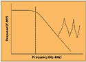
Low-level amplifiers are notoriously vulnerable to radio-frequency interference (RFI). Because of a combination of an out-of-band response and rectification in the amplifier, the low bandwidth of the amplifier is not sufficient to mitigate the problem. According to theory, the input amplifier has a low-frequency cutoff (typically in the audio-frequency range). In practice, however, the textbook model works only for a couple decades of frequency. After that, parasitic elements start to become significant. These elements include input and internal capacitance and path inductance, which combine to form resonances that result in an out-of-band response (see Figure 2). The amplifier suddenly starts to amplify way above the nominal bandpass of the amplifier, responding to even very modest signals.
|
Figure 2. High-frequency resonances in amplifier circuits result in an out-of-band response. |
Low-level amplifiers are also susceptible to rectification. All amplifiers have some degree of nonlinearity, usually controlled by negative feedback. However, the dynamic range of the input signal is limited. When the input signal level reaches the maximum range defined by the voltage and ground limits, rectification is inevitable. In practice, nonlinearity starts to show up well before these limits are reached.
Here is an example. What if an amplifier, looking for a signal of perhaps 10 µV, is hit with 10 V of RF, say from a handheld radio transmitter? Will the amplifier respond? Yes, but in an unpredictable manner. Don't count on common-mode rejection in an amplifier—it ceases to be effective at radio frequencies. The result is that the amplifier acts like a detector, producing a demodulated output. This problem is common even in industrial electronics working with millivolt signals, so it is not surprising that a microvolt amplifier will be affected even worse. Two methods—cable shielding and signal filtering—can solve the problem.
Cable Shielding
Cable shielding is far and away the most effective method of protecting signals. Good shielding techniques will easily produce attenuation of 80 dB or more. This translates to a 10,000-fold reduction in interference. It is possible to produce further attenuation if needed; the amount is limited only by physical constraints, such as the diameter and weight of the cable.
Good shielding effectiveness requires that both ends of the cable shield be circumferentially grounded to the enclosure. Single-point grounding is appropriate only for audio frequencies where the cable length is a small fraction of a wavelength. Although the patient leads may be looking for an audio signal, the RF imposed on the cable is significantly higher in frequency, and it is the RF that the shielding needs to block.
Wavelength is determined by the equation c = fλ , where c is the speed of light, f is frequency in Hertz, and λ is the wavelength. This can be converted into a more usable relationship:
300 = fλ.
To illustrate, consider a readily available handheld transmitter operating at 150 MHz, which has a wavelength of 2 m. (UHF-band radios operate at about 450 MHz, which is an even worse case.) A rule of thumb is that a cable shield should be grounded at both ends if the length of the cable is greater than 1/20 wavelength, which would be 10 cm for the 150-MHz source. Clearly, any patient cable would need to be much longer than that.
It is impossible to terminate the patient end. So, the only solution is to use a single-point ground at the equipment end. This creates two antenna effects: a loop antenna is created at the patient end, resulting in differential-mode interference, and a dipole antenna is created along the entire cable, coupling currents to the signal lines and giving rise to common-mode currents. Common-mode currents are the hardest to fix. They seriously limit shielding effectiveness. Although shielding effectiveness varies with the frequency, this situation produces a worst-case scenario at n/2 + ¼-wavelength intervals (¼, ¾, 1¼, etc.). At these frequencies, the shielding effectiveness is no better than a factor of two, which is hardly worth mentioning.
Depending on the design of the device, there may be leakage-current limitations on the cable as well. Leakage currents from line power (50 or 60 Hz) pose an electrical shock hazard, especially when the device is connected to the patient. The allowed leakage is sharply limited, and this makes EMI filtering difficult to achieve. That problem is addressed in the next section.
Filtering
When a signal can't be shielded, it must be filtered. In theory, this task is not too difficult because there is plenty of bandwidth headroom.
For example, say that there is a signal bandwidth of 10 kHz (most cases will be much lower than that). The lowest radiated test frequency in most requirements is 80 MHz, which means there is approximately five decades of frequency to roll off the interference. For a single-pole filter, there is 20 dB of attenuation per decade of frequency, or 100 dB for this case.
The amount of attenuation needed varies with the connection, but a simple rule of thumb is that for an incident RF of 3 V/m, 3 V is picked up in the cable.
Assuming 100 dB of attenuation, 30 µV will pass through the filter. And this might be good enough, depending on the actual signal levels, noting that this much noise will not drive the first stage into nonlinearity, so rectification will not occur. But parasitic resonances at higher frequencies (above 100 MHz) will effectively degrade filter performance, so care must be taken in filter design.
So, what's the problem? In short, leakage currents. There are two methods for addressing high-frequency leakage: high series impedance to block the currents and low shunt impedance to divert the currents. Of the two, the most effective filtering method is shunt capacitance to the enclosure case. Unfortunately, this creates a leakage-current problem. Depending on the design of the device, only up to a total of 100 pF of capacitance is allowed, which produces a shunt impedance of about 30 Ω at 80 MHz. That means a lot of series impedance is needed to make an effective filter. It is easy to get a lot of impedance if the device can tolerate series resistance, but it is much more difficult if the device needs to rely on inductance.
So, the next step is to consider how to filter the noise without running capacitors to the case ground.
Possible Solutions
Having cited the problems, it becomes clear that there are really no good solutions. But there are some methods that can help achieve the best possible protection. To determine the best solution, it is important to first look at the constraints. As mentioned previously, it is impossible to make a good shield. However, it is still possible to make some gains.
Shielding. The first decision is to determine whether the shield can be grounded at the instrument or whether this would create a leakage-current problem. The shield should be grounded to the enclosure and should be run as close to the patient as possible. The preferred method of terminating the cable shield is to terminate one end directly to the enclosure to place the other end of the shield close to the patient (see Figure 1).
The second decision focuses on the cable shield itself. If the shield can be grounded, the only energy that can get to the signal lines in the cable comes from two sources:
• Through the patient loops.
• From capacitive coupling from the end of the cable shield into the signal lines.
Leakage through the cable shield itself is unlikely to be significant in any real-world situation.
The capacitance from the leads to the cable shield may be excessive, creating a leakage-current problem. If for this reason the cable shield can't be grounded, it may be possible to capacitively ground the shield with, say, 100 pF. This is not a lot of capacitance, but even a little bit helps, especially at frequencies above 100 MHz. Finally, if the shield cannot be grounded to the enclosure, it may be possible to ground it to isolated ground. Any of these options is preferable to floating the cable shield. If it is impossible to terminate the shield, then the best option is to eliminate it.
Filtering. It is already clear that it is best not to run capacitors to the enclosure ground; however, it is possible to filter to isolated ground. The first order of business is to limit the current to the isolated ground as much as possible. Series resistors are preferred wherever possible. It is easy to get a lot of impedance in resistors, and the impedance is constant over a wide frequency range. Ferrites should be considered as a second choice. They are typically used if the direct-current drop cannot be tolerated, as would be the case in power feed. Wound inductors should not be considered. They are guaranteed to resonate at an unacceptably low frequency.
Impedance must also be put in signal ground. A resistor should be used if possible; otherwise, a high-impedance ferrite should be used. The idea is to limit the total amount of current that is dumped into the isolated ground.
|
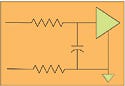
Figure 3. A series resistor followed by a shunt capacitor. |
The signal lines need a capacitor to the circuit ground (which will be isolated ground in this case). Figure 3 shows a series resistor followed by a shunt capacitor. Use as large a resistor as is feasible, and set the cutoff frequency to the signal bandpass or a little above. Mount the capacitor for minimum effective series inductance. Keep the lead length to zero, if possible. The vias and the package itself will give 1–2 nH of inductance, so it is imperative to avoid making it any worse. Low-inductance capacitors, such as surface-mount-technology feed-through capacitors and X2Y capacitors, work well for this application.
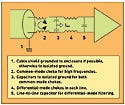
If the situation does not allow for the use of series resistors, then the next-best option is to use ferrites. The particular arrangement of the ferrites is driven by the patient cables. If most of the pickup is through loose patient leads, then differential-mode filters will be the most effective. If most of the pickup is through the cable bundle, then common-mode chokes will be more effective. In all probability, the setup will require a combination of both, in which case the preferred method is to first filter as much common-mode current as possible, followed by the use of differential-mode filters (see Figure 4).
|
Figure 4. An example of a design for filtering common-mode and differential-mode interference. Most patient-connected systems will require a combination of methods to filter both types of interference. |
Filters must be laid out so that they minimize coupling with adjacent input lines. Even a small amount of stray capacitance (as small as 1–2 pF) degrades the performance at frequencies above 100 MHz. In fact, it is not uncommon to have good filters fail to perform because of poor circuit board (PCB) layout.
Some situations can benefit from the addition of a chip shield to minimize the ability of stray fields to get directly to the chip.
Isolated Ground
Applied correctly, the methods described in this article will protect a signal through the circuitry on isolated ground. That's a good start, but it is still usually necessary to get the signal over to the nonisolated side of the circuit board.
It is crucial to minimize the amount of common-mode current remaining on the isolated ground area. This current can be minimized by draining off as much current as possible through the shield and by minimizing the amount of current that gets into the isolated area. The question is how much can the isolation circuitry handle? A typical isolation circuit may have 0.5 pF of capacitance, which is pretty good, but the PCB will still have some stray coupling paths across the barrier. There are two ways to address the problem.
First, it is necessary to minimize the stray capacitance between the isolated ground and the circuit ground. Although the isolator may have minimal capacitance, it is still important to consider the capacitance between the two grounds. Keep as much spacing as possible between the isolated and the nonisolated ground planes. Avoid placing high-profile components too close to the boundary. Finally, look for stray metallic members near the boundary.
The second way to address this issue is to decide whether there is any leakage capacitance left over. If a capacitor has been used on the shield ground, the capacitance may be used up. However, if a cable shield is not being used, there may still be some capacitance available for filtering. Current from the isolated ground can be shunted down to the enclosure ground. This is effective, assuming that the main circuit board is not grounded to the enclosure ground.
An increasing number of engineers are working with plastic enclosures with no shielding, which leaves even fewer options. It is advisable to make enclosure choices with extreme care. Medical device engineers must budget a lot of time and money to work around this problem. In the end, solving the problem may be nearly impossible. As the use of plastic enclosures increases, so does the need for shielding.
Conclusion
Protecting input signals from patient leads is a major challenge. Engineers must pull out all the stops when working on this problem. Even with much preparation, engineers will find themselves redesigning patient-connected devices several times. However, rework time can be minimized by following a few basic rules:
• Current should be diverted as much as possible by grounding the cable shield, preferably directly, or alternatively through a small capacitor.
• Current that can't be diverted from getting onto the cable should be blocked as much as possible from getting to the input amplifier, using as much series impedance as possible.
• The remaining current should be shunted away from the input amplifier, diverting it to isolated ground.
• Coupling paths between adjacent filter components must be minimized through careful layout.
• Coupling paths from the isolated ground to the main circuit ground need to be minimized.
There will be cases in which it is simply impossible to eliminate all of the EMI. In such cases, engineers may have to specify that the equipment operate in a quiet area or, in an extreme case, in a shielded room.
William D. Kimmel and Daryl D. Gerke are principals in the EMC consulting firm Kimmel Gerke Associates Ltd. They can be reached through their Web site, www.emiguru.com.
Copyright ©2006 Medical Device & Diagnostic Industry
About the Author(s)
You May Also Like