


Sign up for the QMED & MD+DI Daily newsletter.
Drawing on the expertise of your molding partners can deliver more effective parts.
11 Min Read

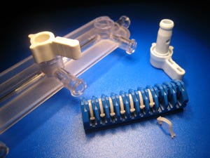
Plastic medical part production presents numerous design and production challenges, including aesthetic and functional design, and manufacturing optimization. A part’s design must be moldable, the mold must be well-planned, and the molding process must incorporate high levels of precision.
|
Turning resin into a well-designed medical part requires careful planning throughout each step of the process. |
While these are important considerations for quality products from any industry, medical parts demand the high levels of expertise. Poor designs can create product flaws that present significant safety concerns for doctors and patients. Any weak link in the design and fabrication processes can compromise the integrity of the final part and lead to expensive redesign.
A collaborative effort is the most effective way for all parties to ensure a part is well designed for manufacturability. In other words, designers should rely on the expertise both of their moldmaking partners (the team that designs, builds, and tests the mold) and their molding partners (the team that will use the mold to produce the part). The most successful parts are produced when the part designer, tool designer, and manufacturer come together to present ideas and input from the earliest stages of development and remain in constant communication throughout the process. Through cooperation, a team of designers can avoid many common molding snags and produce more efficient and cost-effective parts. This article will demonstrate how a collaborative approach can deliver positive results.
Confirming the Part Design and Material
Part design is the starting point for producing a quality finished piece, driving the entire product development process and setting the course for mold design and production. There are many features of a part’s design that, although it may look good on paper, can hinder the toolbuilding and molding stages. Early collaboration can identify, correct, and accommodate any problems before they become more significant.
Here are some things to consider during the design stage.
Wall Thickness. Incorporate consistent wall thickness into the part design to minimize imperfections, such as sink marks, warp, or voids.
Sink marks. Slight dips in the surface of a part. They are a common part imperfection caused by insufficient packing due to inconsistent wall thickness. Generally, a part should be gated thick-to-thin so that the last area to pack out is at the gate end of the part. That way, the gate end freezes off last and ensures adequate packing throughout the part.
Warp. Similar to sink marks, warp is another type of distortion to a part’s surface. Whereas a sink is more localized, warp generally occurs over an entire part. It’s also usually the result of inconsistent wall sections, which cause temperature variations during cooling.
Voids. Voids are internal imperfections in a part that occur most often in thick-walled areas. They occur when there is a significant difference in cooling rate between skin and core material. These imperfections aren’t as physically apparent as sinks or warp, but they can be identified through creating a physical cross-section of the plastic part or x-ray.
Durability. It’s also important to consider the durability of the part upon ejection from the mold. Avoid incorporating delicate, fragile features that have a tendency to break during the ejection process.
Gating. Although gating is more concerning to the mold designer, part designers should also be aware of gate design. Determine if the part is able to have gate vestige, and if so, the best placement of the gate. If possible, gates should be located at the thickest area of the part, so plastic flows from there to the thinner sections. Otherwise, it’s difficult to pack out the thick areas.
Material Selection. Certain materials do a better job than others in filling out certain wall thicknesses. Many materials have a more uniform shrinkage than others. This property also influences the quality of the final part because a more uniform shrinkage equals lower warp, which is caused by differential shrinkage. Combined with these items, knowledge of the end-use application and related requirements are extremely important.
Example: Polyvinyl chloride (PVC) has a higher viscosity than liquid crystal polymer (LCP). If a molder tries to use PVC to make a part that is traditionally constructed using LCP, he will have difficulty filling out the wall. The resistance of flow of the higher-viscosity PVC will inhibit the material from filling in the thin areas. Designers should talk to an expert who has knowledge of the properties of various materials for advice on which materials are appropriate for a given application.
|
Early and constant communication among the part designers, tool designers, and molders is critical to the success of a project. |
Mold Design and Fabrication
The moldmaker is generally the one driving the mold design process. At this stage of the game, he should also work closely with the molder and part designer.
Once the part design has been finalized, the mold design team can discuss how to best mold it and sketch the initial blueprint for the mold using CAD software. With the software as a guide, they can easily react to any changes that may affect the part design, material selection or cavitation, and adjust the mold accordingly. The following are a few important things to evaluate during the mold design stage:
Moldability. To design a good mold, a moldmaker must first ensure that the part design is physically moldable. Occasionally, it’s possible to design a part that can’t be molded.
Mold Steel. Be sure the steel can be fabricated according to the mold design. The steel can behave differently during fabrication than assumed during design. Designers must ensure the steel is thick enough to withstand the injection process.
Wall Support. Insert steel thickness, adequate support below cavity plates and interlocking through bypass shutoff areas are critical as deflection can occur under molding pressure which will likely cause flash and excessive reoccurring maintenance costs. When designing a mold, these are important considerations that need to be well thought out upfront.
Alignment. Alignment is another key to a well-designed tool. When molds close, all components must align properly. Any misalignment will lead to premature wear and related product defects. A proper combination of stock alignment components such as leader pins and bushings, parting line locks, and internal cavity interlocks are generally necessary to minimize future problems.
Wear. Over time, all molds wear out and need sections replaced or repaired. Tool designers must evaluate which parts of the mold will wear out most quickly due to abrasion from the molding material and repetitive shutoff areas. By identifying these sections, they can build spares during the initial tool fabrication and subinsert the particular area of concern for efficient tool maintenance. That way, the sections can be quickly replaced when necessary, significantly reducing downtime or interruption of production.
Scientific Molding Process
Once the mold is built, a molder should run samples of a part to ensure functionality and correct molding.
Some molders use scientific molding to optimize the process and ensure consistent, repeatable production. Through scientific molding, process engineers determine both the optimal molding conditions and the molding window before proceeding into production. Real-time production monitoring systems and advanced quality inspection equipment enable the manufacturer to measure the consistency and efficiency at any point in the production process. These systems work with automated containment controls to divert suspect production and provide historic traceability for the high-end applications in fields such as such as aerospace and medical devices.
|
Engineers must closely evaluate the manufacturability of a part, considering the process conditions with respect to the limits of the injection molding machine. |
After determining the optimal molding conditions and molding window, a first article inspection is generally completed to measure all product specifications. Depending on the application, a capability study may be completed to evaluate critical dimensions over an extended production run. This study enables them to detect any variations over a longer period and adjust the tool or production print accordingly.
Additionally, a molder can often use the design of experiments (DOE) process during preproduction planning to test the limits of the process or to assign a molding window and assess its effect on a measurement, part attribute, etc. DOE also helps gauge the repeatability and reproducibility of the measurement system.
Another common monitoring component is a cavity pressure sensor, especially for high-volume or critical end-use applications. For short-shot detection and other common molding defects, the sensor is usually installed opposite the gate end of the mold and close to the last section to fill. Most sensors have predetermined levels. Otherwise, the molder can set a threshold on the sensor, generally a low limit for short shot and a high limit for flash. For closed loop control, a combination of both gate and opposite gate-end sensors are generally used to make changes on the fly adjusting for machine fluctuation (injection pressure, etc).
If the pin and the cavity sensor on the mold don’t register the required pressure, the press will automatically divert the part with a chute or conveyor. This action lets the molder know whether a part is good or bad before the mold even opens. For closed loop control, the press will make adjustments to compensate for inherent viscosity changes to ensure consistent packing in the cavity occurs.
The Benefits of Collaboration: A Case Study
A global medical OEM recently found success through collaboration. The company wanted to explore molding options as a more cost-efficient method of producing a part for one of it’s medical parts. The part had previously being made from brass and machined, a costly and time consuming process.
The OEM contacted moldmaking and molding sister companies to determine if converting the part to plastic could provide the cost savings that it sought. The companies worked together and started the evaluation process.With prints of the part, they developed two potential options to explore—a single piece with molded threads or a two-piece molded assembly. The initial review effort included a face-to-face meeting with the OEM’s engineers and material suppliers to develop comprehensive risk assessments and material recommendations for both production options.
Further analysis by both parties revealed that the molded-in thread option would require a tougher, more robust material to help prevent the threads from tearing during the final production process. This option translated into more expensive raw material costs, a higher risk tool design, and inherent difficulty to fill out the threads with the preferred resin during the molding process.
Instead, the moldmaking and molding partners recommended another option—molding the part and then installing a separate threaded component with little complexity and cost. This option enabled the team to pursue a less expensive and more familiar material, the ability to incorporate regrind, and a simpler mold design, all of which resulted in further cost savings for the project.
It was the ideal solution for the customer, and it probably wouldn’t have been achieved without all parties collaborating and being involved in the process.
This example makes a strong case for the participation of all players from the earliest stages of a project. As stated, the most successful parts are produced when the part designer, tool designer, molder, and in this particular example, the material supplier, come together to present ideas and input from the earliest stages of development and remain in constant communication throughout the process.
So before you begin your next project, find knowledgable partners, trust their expertise, work closely with them through all stages of the process and keep the following takeaways in mind:
Part design sets the course for every other stage of the process, so identify, correct, and accommodate any problems during this stage before they become more significant later.
Evalute your material so you have a thorough understanding of shrinkage, how it fills out certain wall thicknesses, etc.
Once the part design has been finalized and it’s time to design the mold, be sure to consider moldability, mold steel, wall support, alignment, and wear.
Once the mold is built, a run samples of a part to ensure functionality and correct molding.
Consider scientific molding to optimize the process and ensure consistent, repeatable production.
| Ryan Katen is engineering manager at Plastikos and general manager for Micro Mold (both Erie, PA). He holds both a bachelor’s and a master’s degree in industrial engineering from Purdue University. He has significant tooling and injection molding experience, with a focus on manufacturing process improvement and optimization.Contact him at [email protected]. |
| Rob Cooney is manufacturing manager at Plastikos. He has a bachelor’s of science degree in plastics engineering technology from Penn State (Erie, PA). Cooney has more than 13 years of experience in the industry in improvement, quality systems, and the scientific molding. He also serves on the Society of Plastics Engineers (SPE) board of directors and is president of the Northwest Pennsylvania chapter of SPE. Reach him at [email protected]. |
About the Author(s)
You May Also Like