Sign up for the QMED & MD+DI Daily newsletter.
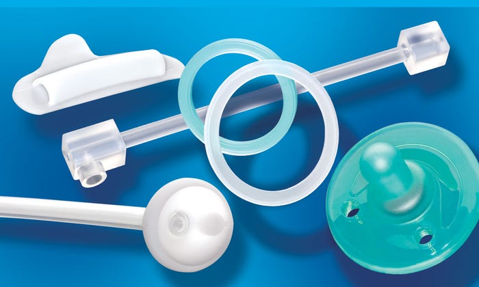
A technician inspects the union of an internal two-part assembled valve and an external LSR overmolded body on a voice prosthesis device.
Pradnya Parulekar
March 1, 2010
12 Min Read
.svg?width=850&auto=webp&quality=95&format=jpg&disable=upscale "Consistency Is King in Silicone Molding")
While design engineers have adopted the highly regimented systems of risk assessment, design validation, and documented protocol submissions, process and manufacturing engineering has been slow to catch up. Unlike many other manufacturing industries that have always been required to provide statistically capable product in order to reduce defects and lower costs, the medical silicone molding arena has been slow to conform, until now. Impending cost pressures, FDA scrutiny, and the burgeoning emerging market suppliers are all factors forcing domestic manufacturers to improve their product performance. Many silicone molding experts have traditionally offered their years of experience to support their beliefs that repeatability is not possible and that tweaking, while not on the process data sheets, is perfectly acceptable, and more importantly, is required for daily production.
Many device industry professionals are familiar with the basic concepts of molding, whether we learned from our mother’s kitchens or through Play-Doh. It involves taking raw ingredients in a malleable form, forcing them into the final intended shape in a container, and then applying a physical treatment (heat and pressure) so that the chemical reaction elicits the desired final physical properties. Silicone molding is virtually the same. Raw silicone, often separated into two parts—one with a catalyst and one without—is mixed and then injected or situated into a metallic mold. After a specific time, temperature and pressure are applied and a solid form of the product, in a cured state, is created. Although silicones can vary in terms of durometers, viscosity, tensile strength, elongation, etc., the methods for producing the parts are essentially similar. Silicone molding is segmented into categories based on whether the preferred substrate is either high-consistency rubber (HCR) or liquid silicone rubber (LSR). The former is used in either compression molding or its more sophisticated avatar of transfer molding, and the latter is used exclusively in liquid injection molding (LIM). This article explores silicone molding and discusses aspects of the process that can help yield high-quality precision parts.
Molding Techniques
Understanding silicone molding and how to maximize its benefits begins with an understanding of molding techniques. A brief overview follows.
Compression Molding. Compression molding was the original method for producing rubber products. Essentially, a premixed billet of material is placed in a cavity that is close to the final part shape. Heat and pressure are applied to mold the part and then it is removed from the press. This method is preferred for HCR materials as well as for parts that are considered low volume (e.g., 1000–5000 per month) and dense in material, because compression molding may not warrant the higher costs associated with LSR tooling.
Transfer Molding. Transfer molding is essentially an improved method of compression molding; it allows for more control of the material size and location as the billet is forced into the cavity via a hopper, thereby regulating the consistency and quantity of the material. It is ideal for HCR parts that are more intricate in shape and for medium-sized production volume.
LIM. LIM, the more glamorous option, is used almost exclusively with LSR materials and requires a specific skill set in both the design of tooling and the processing of material. Both mold makers and press operators need to have a keen understanding of the nuances associated with undercuts, proper venting, surface finishes, steel choices, and press capabilities in order to produce consistent, functional parts. As with HCR processing techniques, LIM provides the most options for OEMs looking to eliminate material waste and create precision dimensions. Waste can be managed with proper tool design—taking into consideration gating locations and flash allowances from the processing perspective. However, a bigger impact can be felt in the method chosen to deliver the material: hot versus cold runner systems. Hot runner systems are the more common method for material delivery. Material passes into the machine via a runner system, passing through various plates that help maintain the material in an uncured state until absolutely necessary, and then is delivered to the mold cavities. Cold runner systems are ideal for low-viscosity LSR materials or products that are unforgiving in terms of wall thickness or flash tolerances. Cold runners use very little material when delivering the silicone to the cavities and, as a result, are considered as close to wasteless as possible. However, cold runner systems are more complex, and this makes them more expensive with a correspondingly long lead time. They are ideal for high-volume operations in which tolerances are tightly controlled.
Overmolding. A more sophisticated molding method involves molding silicone onto another nonsilicone product. This is known as overmolding and is commonly defined as when one substrate is completely covering another substrate through a single-shot or two-shot procedure. The primary substrate to which molders are being asked to overmold is silicone. In addition, a host of new substrates on the market are pushing the boundaries of tool design and material properties. For example, materials such as titanium, PEEK, wovens, and other elastomers are being considered for the next generation of medical products, especially if the molding process can eliminate costly assembly and or secondary operations.
Process Improvements
Silicone molders have discovered that minor tweaking may have incredible repercussions on the characteristics of product
|
Medical device components and healthcare products can be produced in a variety of LSR and HCR silicones via scientific molding and lean manufacturing. |
performance. The highly precarious relationship between process and part has helped spur a highly competitive market for custom silicone manufacturing. Specifically, scientific molding focuses on understanding the cause-and-effect relationship between several key components, including temperature, pressure, and holding times, as well as an understanding of tool design and material properties. Stringent requirements from highly diversified medical OEMs and the influx of process, mechanical, and elastomeric engineers into the field have driven this trend toward process adjustments.
To take the mystery out of silicone molding, a numbers-driven conversation has to take place between the OEM, the silicone supplier, and the mold maker. In order to achieve a consistent product with routine process parameters, the group must discuss the location of gates and parting lines, tool life, and material shrink rates. These elements define the tool design. Silicone, regardless of the durometer or brand, has a reputation for being a highly abrasive material and may exacerbate the natural wear of a tool. For example, this can be witnessed in the migration of dimensions to either end of the bell curve as gates and shut-off areas become worn or washed out.
An effective design for production tooling begins in the prototyping phase. Some would say that the medical device industry has been slow to see the benefits of prototype tooling outside of the R&D lab. If the industry indeed lags behind other industries in this regard, it is due in part to the rush to bring products to market, the OEMs’ typical need for low volumes, and interpretations of FDA requirements. These factors sometimes make it a daunting task to persuade OEMs to invest in prototype tooling prior to ordering production tooling. Prototype tooling allows process engineers and quality departments to anticipate potential production problems with respect to maintaining critical dimensions. Occasionally, manufacturers find themselves needing to move forward with the prototype tooling as a means for speeding up production and meeting market demand; this can result in implementing less-sophisticated aluminum tools, which may result in a rapid decline in the quality of a molded part.
The rapid improvement and availability of quality manufacturing presses and precise machinery has aided the progress of silicone molding. The latest presses provide manufacturers with real-time information that can be used to provide immediate feedback about the approved molding parameters. Any deviation can be immediately addressed by the process engineers, which prevents the accumulation of defective product and potential consternation for the manufacturer. The major press manufacturers have customized their machinery so that the information being gathered is relevant, precise, and specific to the product.
Improving Consistency
How can the medical molding world benefit from these improvements? The old adage “the customer is always right” is not just lip service for contract manufacturers, but one would be remiss not to suggest ideas for ease of manufacturability. The initial drawing request for quotation should be considered an opening bid for a successful product launch. This is the opportunity for the cost estimator or sales engineer to truly understand the product’s application and the necessary requirements, and then determine how those needs can be met in a manner that improves consistency and reduces cost. Many CAD programs automatically calculate the “perfectness” of a part and provide dimensions that are expensive to achieve in the real world. For example, the stack-up calculations in a CAD program actually result in overtolerancing a part. The true position center of a diameter is plainly seen on a CAD model, however, this same true center is not plainly defined on actual parts, no matter how sophisticated the measuring apparatus. The key considerations that can help improve consistency in manufacturing and that will ultimately lead to better management of product performance in silicone molded parts include the following.
Allowable Flash Considerations. Probably no aspect of silicone molding irks both the manufacturer and the supplier more than flash. Many initial drawings are discussed with the notion that no flash is allowed. Due to the nature of silicone, a set amount of flash is going to exist as the part is removed from the mold; just how much is allowable is defined in terms of visualization and function. High-precision tooling and gating technology can be used to help control the shut-off areas. However, that usually requires considerable capital investment and patience with the delivery dates. This type of technology, while not patented in theory, is proprietary with respect to each tool house and requires extensive design and machining time. Thus, mold delivery requires more time (eight versus 16 weeks, for example). The quick-fix way to deal with undesirable flash tolerances is to perform costly and time-consuming secondary operations such as manual flash removal or cryogenic deflashing. Both options not only introduce additional cost and cycle time, but also extra operations used to counteract any chemical and human involvement.
Gate and Parting Line Locations. An unattractive parting line may call undue attention to an area that is not really functional. Therefore, the manufacturer should determine where parting lines and gates are not permitted in order to find out the best location for a gate. Gating was traditionally decided by the method in which the mold could be made most easily. Many years of defective parts have taught mold makers that gate size, quantity, and location are the keys to a well-balanced mold and properly filled parts. Because silicone is a particularly abrasive material, the contract manufacturer should regularly inspect the molds to ensure gate wash-out has not occurred. This can be properly anticipated through the statistical data taken by quality control.
Overmolded Materials. Metals, plastics, and even other rubbers are all fair game for silicone overmolding. What needs to be carefully considered is the strength of the bond and what metric of shear or pull testing will be required to determine functionality. For example, some strain reliefs have silicone over plastic to aid in function, but if the port is subjected to a lot of friction, the silicone could experience an adhesive failure. Some manufacturers will require a pull test on the elastomeric to metal or thermoplastic joint to ensure that there isn’t an adhesive failure. A safety factor of three (test result is three times the minimum required force in application) is a minimum requirement. More often than not, a chemical primer or adhesive will have to be considered on materials such as PEEK or plastic.
Radii, Chamfers, and Dimensions. Silicone’s main component is silica, which is commonly found in nature as sand or quartz. It is a highly abrasive compound that slowly wears away at even the most durable metals. In addition, silicone cannot take on a perfect shape if sharp corners are desired. A radius will always form in the block of a corner. Therefore, unless secondary operations are performed, designers should consider curves instead of edges when working with silicone. Sometimes a chamfer is used to improve port removal. This chamfer can potentially be used for the final design as well. Overall, OEMs should communicate the importance of critical dimensions and compromise whenever possible.
Quality Inspection Expectations. A discussion of the quality inspection criteria is probably the most important conversation a supplier and an OEM will have. Understanding the capabilities expected on critical and noncritical dimensions should be the cornerstone of every product launch meeting. Both parties’ measurement systems should be properly calibrated (with either MSA, measurement system analysis, or GRR, gauge repeatability and reproducibility) so that there is no confusion once the product is launched.
Lot Sizes and Schedules. Some manufacturers gravitate toward high-cavitation molds as a method for cost control; however, high-cavity tools are often too complicated to allow precise control and may require runner systems and mold designs that are cost-prohibitive. As a result, many manufacturers look for more affordable ways to produce a 32-cavity mold and then often find themselves creatively managing failing cavities as the mold wears. By keeping molds to a modest cavity size, the cycle time improvement can often offset any price break perceived from molds with more cavities. Smaller cavitation and standardization also allows for quick changeovers. The smaller size molds will allow for quicker start-ups and first-shot measurements. In turn, this can improve flexibility in production scheduling, thus reducing lead times for production parts.
Conclusion
Although silicone molding is not new to the medical device industry, mold makers and manufacturers are continually making adjustments to improve the consistency of final parts. Silicone traits such as durometer, viscosity, and tensile strength may vary, but the methods for producing the parts are similar. Effective communication with suppliers about gates and parting lines, lot sizes, flash, and other critical elements of molding can help OEMs to produce high-quality precision parts. This can also improve overall product performance and end-user satisfaction in the process.
Pradnya Parulekar is custom manufacturing services brand market manager at Helix Medical LLC (Carpinteria, CA).
About the Author(s)
You May Also Like
Editors' Choice


.png?width=300&auto=webp&quality=80&disable=upscale)
Sponsored Content
May 23, 2024