Sign up for the QMED & MD+DI Daily newsletter.
Experts explain how thermal imaging cameras can be used to debug complex circuit boards, a tricky, time-consuming part of medical device development.
October 21, 2016
7 Min Read

Experts explain how thermal imaging cameras can be used to debug complex circuit boards, a tricky, time-consuming part of medical device development.
Jason Christensen and Andreas Pfahnl, ScD
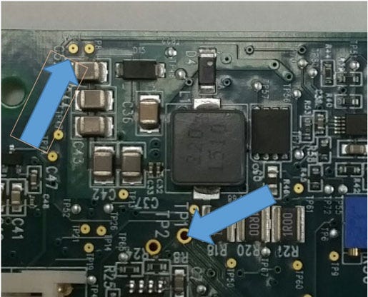
Figure 1: PCBA with example test and access points highlighted
Reduced time to market has put pressure on all aspects of medical device development. Many medical devices today are electromechanical involving PCBA's or "boards." The boards are inherently difficult and time-consuming to debug because of their complexity and amount of integration. We have found a thermal imaging camera an effective and time-saving tool to debug complex circuit boards.
Background and Access Limitations
There are significant limitations to being able to characterize a board and even specific circuits on a board. Test points and surface mounted components with external leads are primarily used for manual probing with an oscilloscope or multimeter (see Figure 1, above).
Take part in product teardowns at BIOMEDevice San Jose, December 7-8. |
In order to probe surface mounted components, they must have accessible leads, which means ball or land grid array components are excluded. Connectors used for board-to-board connections are sometimes also used to gain access to specific circuit sections, but greater use of rigid-flex reduces physical interconnects, further exacerbating the integration challenge, time-consuming probing, and probing access.
Identifying Failed Components
In the development of a PCBA design, the first fabrication of a board is really the first chance to verify the design. A board can have damaged components from the assembly manufacturing process or incorrect connections in the design, resulting in problems like over-voltaged components or shorts to ground. Not all issues can be identified during a careful bring-up. When a board is powered, issues on a board can cause components to get stressed to the point the power supply "crowbars" and overheating occurs. If the problem is significant enough, the failure can be visually identified (smoke!). Other times, the problems are more subtle, perhaps affecting multiple integrated circuits (ICs) on the board. This is when using a thermal imaging camera along with a digital multi-meter can enable rapid identification of the area that needs attention.
Generally speaking, the first component to be damaged on a PCBA is an integrated circuit (IC). These types of components, digital logic, operational amplifiers, and all the low voltage components are less tolerant to overstress, especially overvoltage. Figure 2 shows an example of a damaged sensor with an embedded IC.
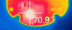
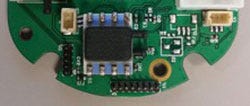
Figure 2: Damaged Sensor
Measuring the impedance of the voltage rails is usually the first step in debugging a failure. If the impedance measures less than 10 ohms, there is almost certainly a problem. But where do you go from there? There could be dozens of parts all on the same power supply, and lifting pins on every one or even removing entire components is a time-consuming endeavor, not to mention the difficulty in reconnecting them. This is where the benefits of a thermal camera or thermal imaging come into play.
The process for using a thermal camera is straightforward. It should be set up on a stand, since a steady shot will help narrow in on the hotspot. Keep an assembly drawing and schematic handy to identify components. Initially, limit the power supply current to prevent any further destruction of components. Turn on the supply and you may see multiple ICs starting to warm up. The brightest objects tend to be regulators, especially linear regulators. Many switching topologies have short circuit protection built in that protects the power supply so that it stays active and continues delivering power to the downstream circuitry. This can cause the regulators to overwhelm the infrared (IR) field and obscure the actual failed components. As a result, it may be necessary to subvert or isolate the power supply by using one that is external to enable the thermal camera to identify the damaged components on the board.
Diodes are generally directly in the power path, and therefore tend to show up rather brightly if a path conducts a lot of current causing the diode to heat up significantly. Figure 3 and 4 show examples. Identifying pathways with higher than anticipated currents can help find a circuit with damaged components.
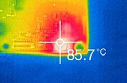
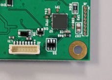
Figure 3: Blown ESD protection diode on a USB bus
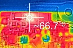
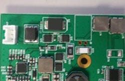
Figure 4: Hot power rectifier diode
If the current is not high enough, then the offending circuit may be difficult to find. Also, if the current increases only a milliamp or two, finding the damaged circuit may not be possible. This is particularly true for very low power designs in the micro-amp range. In these cases, lifting individual pins on ICs may be the best approach.
Identifying Misconnections and Other Failures
In addition to identifying failed components on a PCBA, a thermal camera may identify unintended circuit design issues. In these cases, the voltage rail impedances may measure fine before power is applied. However, once power is applied, the power supply current increases to excessively high levels. The power supply should be turned off quickly to save the circuit and prevent components from reflowing off the board. Now using a thermal camera will help identify hot components. For example, two output pins may have been connected inadvertently and are improperly trying to drive each other. This would cause both connected ICs to heat up and be quickly visualized with a thermal camera. Cut-and-jumper rework can then resolve the issue.
Other examples of how a thermal imaging camera could be useful:
Erratic power cycling may be causing a microcontroller and an input/output (I/O) expander to initialize in a non-deterministic state, causing high current draw. The resulting elevated temperature of the microcontroller and/or the I/O components would be identifiable with thermal imaging. Not allowing the logic to fully reset during a brown out condition may have caused this to happen. Using a voltage supervisor or power on reset circuit is a way to prevent this.
Units may be failing after extended environmental tests. The power supply current seems high and nothing else seems functional. Thermal imaging shows that only the power transistor in a switching supply is getting hot and nothing else is. Measuring impedance with a multimeter shows lower resistance on the power rail leading to the identification of the root cause being flux contamination under the surface mount capacitors, causing a short circuit-like effect.
Equipment Options
There are many cameras on the market, ranging from $100 to $20,000. The price variance is driven by the types of features and the performance specifications, including the ability to measure temperatures, save pictures and videos, and combine the thermal and optical images. There are cameras that can plug into your smart phone and are very helpful in finding hotspots. A couple examples are shown in Figure 5.
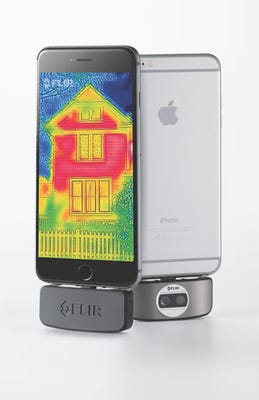
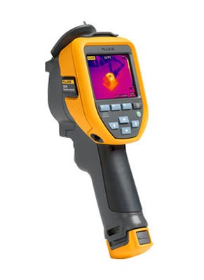
Figure 5: Examples of thermal cameras. Left is FLIR Smartphone Camera. Right is Fluke TiS10.
Thermal imaging has proven to be a very valuable tool to more rapidly bring up and debug PCBAs. They can be used to identify failed components or incorrect trace connections, which manifest themselves in hot components or elevated subcircuit temperatures. Thermal cameras needed for this purpose are small and very affordable, and nicely complement the use of multimeters and oscilloscopes.
Jason Christensen is a senior electrical engineer at Devicix, which is the engineering services and product development group of Nortech Systems Inc--Medical Devices. His expertise is in new product circuit design and simulation. Nortech Systems, Inc. is an international contract medical device product development and manufacturing company with ISO 13485 facilities and locations in Minnesota, Mexico, and China.
Andreas Pfahnl, ScD (VP & CTO) is vice president and chief technology officer in Nortech Systems Inc--Medical Devices.
[Images courtesy of NORTECH SYSTEMS, INC., FLIR SYSTEMS, INC., AND FLUKE, INC.]
You May Also Like