


Sign up for the QMED & MD+DI Daily newsletter.
DIAGNOSTICS
Niels Wartenberg
March 1, 2008
17 Min Read
.svg?width=850&auto=webp&quality=95&format=jpg&disable=upscale "Considerations for Embedding Cap Inspection Systems")
DIAGNOSTICS
|
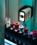
Figure 1. Cap inspection enables devices to identify the tube and cap type. Photos courtesy of MICROSCAN SYSTEMS INC. |
Cap inspection systems provide critical information that helps streamline diagnostics automation and limit medical mistakes. The systems help automate tasks that are currently performed by laboratory personnel by providing data for diagnostic devices and laboratory automation systems. They can also provide additional safeguards against process errors.
Many devices currently on the market can perform cap identification. The majority of the products available for device designers are quite complex—sometimes the devices require up to 10 sensors to accomplish some of the same tasks that could be accomplished by one imaging device. To simplify the design process, designers can integrate a miniature imager.
Vision Recognition
Device manufacturers are already eliminating a leading source of errors by using bar codes, which automate data entry and data reporting processes.1,2 Yet there is still room for innovation. Cap inspection takes the tube identification process a step further by enabling diagnostic devices to prevent automation mishaps caused by sortation and organizational errors.
Imaging technology similar to what is currently used to read bar codes. An imager designed for cap inspection can provide the diagnostic device with critical information that can be used to identify the tube and cap type before tests are performed (see Figure 1). This ability is especially useful in automating the initial receipt of specimens into the laboratory. Having detailed information about each tube and cap allows the fluid aspiration process to be streamlined, preventing pipette crashes and automating tube sortation by using shape recognition and color identification.
The resource commitment involved in adopting a cap inspection system is dependent on the scope of the application and the type of imaging solution selected to collect the data. Imaging devices vary significantly in their capabilities and suitability for embedded applications. Understanding their strengths and limitations is essential for finding the best component for a specific device.
Vision recognition systems have previously been composed of four separate components: a camera, decoder, frame grabber, and light source. These systems were notoriously expensive and challenging to integrate. Vision technology has continued to evolve, and today these separate components have been fully integrated into a single compact unit.
|
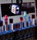
Figure 2. Miniature imagers incorporate vision capabilities such as shape recognition and color identification with a wide field |
By combining megapixel technology with vision capabilities such as shape recognition and color identification, miniature imagers give designers access to the key functionality of a vision system with a footprint and price point that make them technically and economically feasible for embedded applications (see Figure 2). For example, some miniature imagers measure approximately 1.8 × 2.1 × 1.0 in. and cost around $3000. A few years ago, vision systems composed of several components often started at $7000 and climbed up from there, depending on the complexity of the application. Instead of a small, fully integrated unit, an engineer would sometimes need to integrate a 4-in.-long camera, a framegrabber or processing platform (approximately 12 × 4 in. or larger), and a separate light source. Miniature imagers perform the image processing for the device and output the data in standard ASCII text, making the data easy to integrate.
|
Figure 3. Multiple optical sensors can be combined to determine tube height during high-speed processes. |
Optical sensors, as their name suggests, are simple optical devices that collect a specific type of data such as color, the presence or absence of particular elements, etc. (see Figure 3). The components are considerably less expensive per unit than imagers or vision systems. Because they do not perform any image processing, they can collect and output data much faster than megapixel imagers. The trade-off in most cases is that optical sensors only provide a rough height measurement and color information from a few predetermined locations. These limitations impose restrictions on the tube types supported and prevent laboratories from having detailed information regarding cap dimensions.
Complex, multicomponent vision systems offer speed and intelligence, but they are not available at a price point that makes them a valid option for embedded subsystems. Consequently, some manufacturers have tried to develop their own vision systems. Designing a system in-house involves developing or integrating image-processing software, which is usually a significant departure from a manufacturer's core competencies. In addition, developing suitable systems may involve a steep and challenging learning curve. The component costs may be comparable to other options, but the system may require an extensive amount of engineering time to operate successfully. Even if an initial design is promising, attaining the required accuracy may prove elusive. Additional concerns include the long-term availability of the components and the potential unavailability of ongoing support for fielded solutions.
What designers may not realize when they undertake building a vision system themselves is that they are starting at 0% read-rate accuracy and must work their way up to 99.89%—the performance level commonly accepted by the diagnostic industry. When a fully integrated imager is integrated into a system, the device achieves a 90% read-rate accuracy simply by powering up the imager. The device design team and the imager manufacturer collaborate to achieve the remaining 9.9% by adjusting the calibration settings and fine-tuning other elements of the system until 99.89% is achieved. Expertise and support from the imager manufacturer can save the device manufacturer hundreds of engineering hours and reduce the total cost of research and development for the device.
Assessing the Resource Commitment
Determining the resource commitment in adopting a cap inspection system involves more than a price-versus-performance comparison. Manufacturers must consider the cost of ownership, the system's accommodations for future applications, its linear bar code system compatibility, and training methods for employees.
|
Figure 4. (click to enlarge) Miniature imagers perform the image processing for the device and output data as standard ASCII text. |
Total Cost of Ownership. The total cost of ownership must be taken into account. This is not just the initial cost of components, but the number of engineering hours required to get the system up to acceptable performance levels. The programming requirements must also be considered, and writing image-processing software can be labor intensive. Miniature imagers perform the image processing and output the data in a ready-to-use format for the device (see Figure 4). The imager completes all the necessary data translation before the device receives the data. In-house vision systems often require the device manufacturer to write image-processing software to extract information from the imager. The amount of programming required for these imaging systems varies by application.
Planning for the Future. The total cost of investment also includes an assessment of how well a cap inspection system addresses current needs as well as how it will evolve to accommodate future applications. It is well known that many diagnostic devices enjoy a long life once installed in a laboratory. Will the image-processing software be able to accommodate ever-smaller sample sizes? How easily can the system be upgraded to accommodate new applications? Upgrading a miniature imager is a simple software change. Updating a multiple-sensor system, however, usually requires a hardware change, which is much more invasive and not as easily accomplished for devices out in the field.
Bar Code Considerations. A miniature imager's ability to read linear bar codes ensures that the device is 100% compatible with existing linear bar code–based systems.
The imager also builds in data capture capabilities for the future, which can easily be enabled by a software command. For diagnostic devices that already have a bar code identification system, considerably less engineering is involved than when manufacturers incorporate an identification system from ground zero. Integrating a cap inspection system simply expands the capabilities of the device. In most cases, the cap inspection imager can serve as a drop-in replacement for the bar code reader. Because miniature imagers have nearly the same cubic footprint as small laser bar code scanners and share the same power draw, changes to the device are minimal. The imagers also offer high-resolution optics, enabling them to be more forgiving of damaged or low-contrast bar codes. They also enable the reading of tiny high-density 2-D codes.
Training Requirements. As with all new technologies, there is a learning curve to be negotiated. Compared with early vision systems, today's imagers are much simpler to use and require significantly less initial programming and training to reach optimal performance levels. However, they still require a certain level of expertise to achieve and maintain high read rates. Imagers also require a rudimentary understanding of optics, lighting, and depth of field, as well as how these elements affect an application. To set up an imager, the implementer must understand how to adjust the gain and the shutter speed. Implementers must also find the ideal compromise between field of view and processing speed. The larger field of view, the more pixels the imager must process to achieve the desired outcome. This results in slower processing speeds.
Training usually begins with an initial product overview. The first session introduces the design team to the product and walks the team members through the basic steps involved in setting up the unit and customizing the imager's settings. An imager is provided to the team leader for several weeks so that the team members can familiarize themselves with the process. This gives them a chance to develop solid, constructive questions based on meaningful experience with the product. After a month, they should be ready for in-depth training sessions. The imager manufacturer should bring in engineering resources, based on the specific application requirements, to help answer their questions and address the issues pertinent to their embedded application. Typically this involves an applications engineer with extensive product experience. In rare cases, an R&D engineer may also be needed.
Project Definition
Device manufacturers must clearly define how the cap inspection system will be used as well as how the data will be interpreted. Project definition includes the scope of the application, acceptance and rejection criteria, and other elements crucial to effective cap inspection systems.
To incorporate a cap inspection system into a device, the scope of the application must be clearly defined. What is the primary benefit to be gained by incorporating a cap inspection system? Will cap inspection automate the sortation of a complex mix of tubes and containers? Will it prevent incompatible tubes—perhaps screw cap or Sarsted tubes—from entering the closed-tube aliquotter? Maybe it will be used to prevent pipette crashes by determining whether the decapping operation was successful.
|
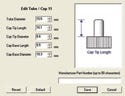
Figure 5. (click to enlarge) Miniature imagers offer a built-in library capacity of up to 100 different tube and cap combinations. |
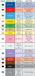
Depending on the type of technology selected, the application possibilities are limited only by the capabilities of the device and its ability to process the data. The cap inspection imager can provide the device with specific measurements of up to 100 different cap-and-tube combinations (see Figure 5). Shape recognition enables the imager to determine the type of cap on the tube in addition to height and diameter information. The imaging system's precise color identification and matching capabilities allow it to identify and sort tubes with varying shades of the same color, such as pink and red (see Figure 6).
|
Figure 6. (click to enlarge) Miniature imagers can identify common cap colors, |
Once the scope of the application has been determined, the acceptance and rejection criteria must be established. In some closed-loop applications, for example, a general measurement may be all that is needed because the operation is standardized on specific types of tubes. For devices used in large laboratories that receive different types of tubes from multiple locations, the data collected must be precise or process errors occur. The scope of the application and the precision that is required should be carefully considered and then matched to the capabilities and limitations of the imaging technology itself.
For example, a typical multisensor system integrated into a tube-handling system designed for cap presence detection only provides height information. Consequently, all the tubes must be within the supported dimensions and properly seated in the rack. A tube of a nonsupported height or an improperly seated tube without a cap may be mistaken for a tube with a cap. In contrast, miniature imagers use shape recognition to determine cap absence or presence (see Figures 7 and 8). As a result, the imagers yield the same absence or presence answer regardless of whether the tube is properly seated. The system is not restricted to specific types of tubes because it uses shape recognition to determine cap presence, not height information. This provides the system designer with additional flexibility and allows a manufacturer's system to handle and process a variety of tube and container types (see Figure 9).
|
Figure 7. Miniature imagers employ shape recognition to |
Lighting plays a vital role in imaging applications and can also be application specific. Imagers provide excellent performance in low-light conditions. In addition, many imagers designed for embedded applications have an integrated light source, usually an array of light-emitting diodes (LEDs). For vision applications that use color identification, white LEDs are preferred because they provide the color-neutral illumination necessary for accurate color identification. Integrated lighting saves the user considerable time and resources, because lighting components are expensive and not easy to set up.
|
Figure 8. (click to enlarge) Built-in image-processing software enables the user to easily set sortation parameters. |
The optimal background behind the object of interest depends on the type of data to be collected. The color of the area behind the object to be captured is particularly important for measurement and color identification. A solid background is required for efficient shape recognition. The preferred color of the background depends on the illumination color and the optical filter used. For example, a black background has proven to be effective with white illumination.
Designers value compact components, and imagers are no exception. However, the space needed within the system to capture the necessary data can be more important than the size of the imager itself. Several different factors determine distance requirements. These include the size of the object of interest, and the imager's field of view and depth of field. If the imager is also reading symbols, the density and type of symbol must also be considered. The challenge in capturing data at close distances is achieving a field of view large enough to capture the entire object of interest. By incorporating megapixel technology, miniature imagers offer designers an exceptional field of view while still maintaining sufficient resolution.
|
Figure 9. By using vision recognition capabilities, miniature imagers allow the device to identify more tube and cap types. |
To simplify integration, miniature imagers output the data in the standard ASCII text format. This way, the data have already been translated and are ready to be acted on. The data format is also compatible with a broad range of laboratory automation systems and laboratory information systems that are supported by both legacy systems and leading-edge informatics.
Setup software makes it easy to select how the data are output. The software provides designers with a great deal of control over what type of data the system receives as well as in what order and format. For example, designers can program an imager to output only the cap color and information from the bar code on the tube. Or, an imager can be programmed to capture entire tube profiles, but output only a simple good read (an output provided when the preset requirements of a read cycle are met). A Windows-based software interface makes it easy to adjust the settings and customize the data parsing.
Failure Modes and Effects Analysis Considerations
Just as with other types of data-gathering methods, the execution of a well-planned failure modes and effects analysis (FMEA) is strongly encouraged with imager-based systems. Encouraged practices include the following:
Using positive confirmation for every process (see Figure 10).
Requiring that the imager achieve more than one determination prior to outputting the result.
Using comparisons between the parameters gathered before and after decapping.
Implementing provisions for redirecting questionable specimens for further, potentially manual, inspection.
The following practices should be avoided:
Using processes in which the absence of feedback is seen as acceptance (i.e., no news is good news).
Reporting data based on a single capture rather than requiring several agreeing determinations.
|
Figure 10. (click to enlarge) Built-in software makes it easy to format data for positive confirmation of processes for FMEA. |
To support FMEA operations, imagers should be set up to send a system a good read message each time the imager reads a bar code or performs a specific task. If the device fails to receive such a message, an alarm can be tripped or the device can shut down until the “no read” is investigated. This ensures that the device will be notified if a negative outcome occurs.
Imagers can provide additional precautions to ensure process integrity. A cap inspection system is often set up to take multiple before-and-after pictures of each step in the process for documentation in case a negative outcome occurs. For example, the imager can take a picture of a cap. The decapper removes the cap, and a second picture is taken to make sure the cap is gone. The imager measures the height of the tube again to document that it has been reduced via decapping. Both shape recognition and height measurement are captured to provide the maximum amount of data for ascertaining the cause of a negative outcome. The additional data are helpful, for example, in situations in which the tube is raised by the decapper but not properly seated after the decapping is completed. If only height were measured, the system could determine that the cap was never removed, or that the tube is a rogue because it has the wrong height. By documenting the entire process with photographs, technicians have the data to discover the nature of the problem if an alarm is tripped.
Regulatory Considerations
Medical device manufacturers must consider the quality of an imager and the quality certification of an imager vendor. Because medical devices undergo intense scrutiny by FDA and other equivalent bodies worldwide, designers must be sure to choose products from responsible vendors.
A vendor should at least be certified to ISO 9001:2000 and the products should carry CE, RoHS, and WEEE approvals or certifications to ensure that the components do not compromise the overall certification of the device.
Conclusion
As with all changes to established processes, integrating a cap inspection system requires careful planning and consideration of the resource commitment involved as well as the effects the new system may have on the device. Unlike many new technologies, miniature imagers are completely compatible with legacy systems and do not render older data-collection systems obsolete. Their unique capabilities allow a system to address today's needs while also building in data-capture capabilities for the future.
Multifunctional imagers also help reduce product cost and complexity by reducing the number of embedded sensors and components needed for a cap inspection system. In the past, incorporating vision recognition into a system would have been a complex process with a minimal return for the considerable drain it would place on resources. Imaging technology has since evolved. Miniature megapixel imagers can provide designers with access to the key functionality of a vision system with a footprint and price point that are economically feasible for embedded applications.
Niels Wartenberg is senior field applications engineer at Microscan Systems Inc. (Renton, WA). He can be reached at [email protected].
References
1. TJ Mark, “Decoding the Bar Code,” ARMA Records Management Quarterly 28, no. 1 (2004): 22–25.
2. PN Valenstein et al., “Identification Errors Involving Clinical Laboratories: A College of American Pathologists Q-Probes Study of Patient and Specimen Identification Errors at 120 Institutions,” Archives of Pathology and Laboratory Medicine 130, no. 8 (2006): 1109.
Copyright ©2008 Medical Device & Diagnostic Industry
About the Author(s)
You May Also Like